3-3
Cisco PIX Security Appliance Hardware Installation Guide
78-15170-03
Chapter 3 PIX 506/506E
Installing the PIX 506/506E
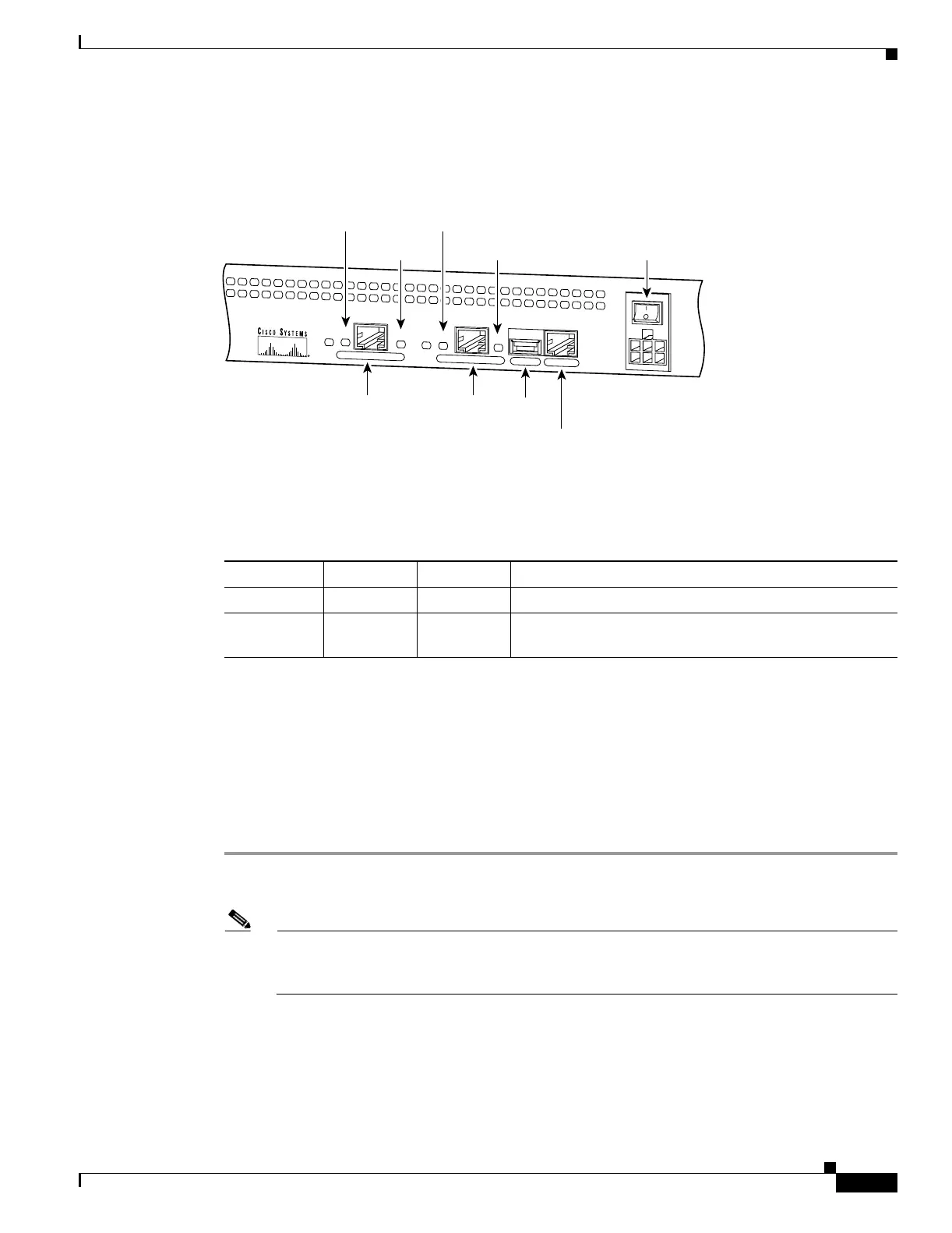
Figure 3-4 shows the PIX 506/506E rear panel LEDs.
Figure 3-4 PIX 506/506E Rear Panel LEDs
Table 3-2 lists the states of the PIX 506/506E rear panel LEDs.
The USB port at the left of the Console port is not used.
Installing the PIX 506/506E
Place the PIX 506/506E on a flat, stable surface. The PIX 506/506E is not rack mountable.
To install the PIX 506/506E, perform the following steps:
Step 1 Connect the cable so that you have either a DB-9 or DB-25 connector on one end as required by the serial
port for your computer, and the other end is the RJ-45 connector.
Note Use the RJ-45 Console port to connect a computer to enter configuration commands. Locate the
serial cable from the accessory kit. The serial cable assembly consists of a null modem cable
with RJ-45 connectors, and one DB-9 connector and one DB-25 connector.
C
O
N
S
O
L
E
E
T
H
E
R
N
E
T
0
ACT
LINK
LINK
DC
POWER
INPUT
ACT
U
S
B
E
T
H
E
R
N
E
T
1
38852
10BaseT
(RJ-45)
10BaseT
(RJ-45)
Console
port (RJ-45)
USB
port
Power switch
LINK
LED
LINK
LED
ACT(ivity)
LED
ACT(ivity)
LED
Table 3-2 PIX 506/506E Rear Panel LEDs
LED Color State Description
ACT Green On Shows network activity.
LINK Green On Shows that data is passing on the network to which the
connector is attached.