4-23
Cisco PIX Security Appliance Hardware Installation Guide
78-15170-03
Chapter 4 PIX 515/515E
Installing the PIX 515/515E DC Model
Installing the PIX 515/515E DC Model
Warning
Before performing any of the following procedures, ensure that power is removed from the DC circuit.
To ensure that all power is OFF, locate the circuit breaker on the panel board that services the DC
circuit, switch the circuit breaker to the OFF position, and tape the switch handle of the circuit
breaker in the OFF position.
To install the PIX 515/515E DC power model, perform the following steps:
Step 1 Read the Regulatory Compliance and Safety Information document.
Step 2 Terminate the DC input wiring on a DC source capable of supplying at least 15 amps. A 15-amp circuit
breaker is required at the 48 VDC facility power source. An easily accessible disconnect device should
be incorporated into the facility wiring.
Step 3 Power off the PIX 515/515E. Ensure that power is removed from the DC circuit. To ensure that all power
is OFF, locate the circuit breaker on the panel board that services the DC circuit, switch the circuit
breaker to the OFF position, and tape the switch handle of the circuit breaker in the OFF position.
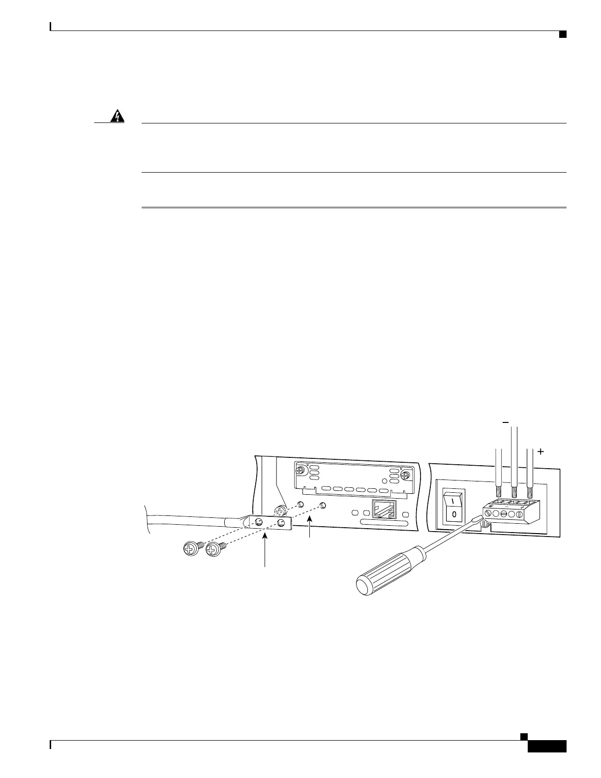
Step 4 As shown in Figure 4-24, the PIX 515/515E is equipped with two grounding holes at the back of the unit,
which you can use to connect a two-hole grounding lug to the PIX 515/515E. Use 8-32 screws to connect
a copper standard barrel grounding lug to the holes. The ground lug must be NRTL listed or recognized.
In addition, the copper conductor (wires) must be used and the copper conductor must comply with the
NEC code for ampacity. The PIX 515/515E requires a lug where the distance between the center of each
hole is 0.56 inches. A lug is not supplied with the PIX 515/515E.
Figure 4-24 Attaching a Grounding Lug to the PIX Security Appliance
Step 5 Strip the ends of the wires for insertion into the power connect lugs on the PIX 515/515E.
Link
FDX
100 Mbps
10/100 ETHERNET 1
27885
Grounding holes on
PIX DC model
Ground wire wire
2-hole copper standard
barrel grounding lug
must be NRTL
listed or recognized
8-32 screws
To r a ck
ground
wire