4 Cisco 220 Series Smart Plus Switches Quick Start Guide
Reset Button—The Reset button is used to reboot or reset the switch with
a pin or paper clip. See Returning the Cisco 220 Switch to the Factory
Default Settings for more information.
System LED—(Green) Lights steady when the switch is powered on, and
flashes green when booting, performing self-tests, and/or acquiring an IP
address. If the LED flashes amber, the switch has detected a hardware
failure, a firmware failure, and/or a configuration file error.
Link/ACT LED—(Green) Located on the left of the port. Lights steady
when a link between the corresponding port and other device is detected.
Flashes when the port is passing traffic.
NOTE The System and LINK/ACT LEDs are on each model of the switch.
The LEDs that follow are only present on the switch models that have
those capabilities.
100M LED (if present)—(Green) Located on the right of the port. Lights
steady when other device is connected to the port, is powered on, and a
100 Mbps link is established between the devices. When the LED is off, the
connection speed is under 100 Mbps or nothing is cabled to the port.
GIGABIT LED (if present)—(Green) Located on the right of the port. Lights
steady when another device is connected to the port, is powered on, and a
1000 Mbps link is established between the devices. When the LED is off,
the connection speed is under 1000 Mbps or nothing is cabled to the port.
PoE LED (if present)—(Amber) Located on the right of the port. Lights
steady to indicate that power is being supplied to a device attached to the
corresponding port.
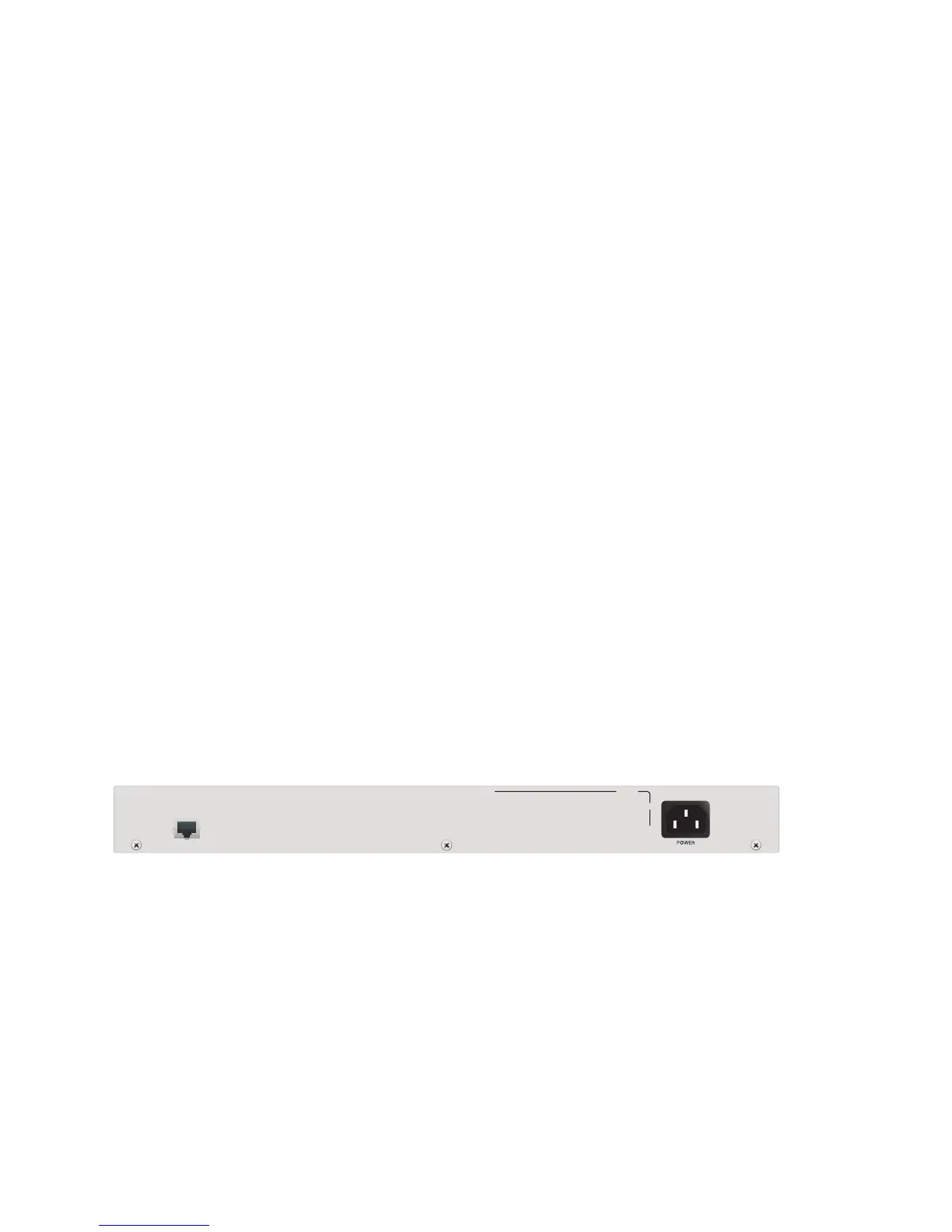
Back Panel
The power and console ports are located on the back panel of the switch.
POWER—The power port connects the switch to power.
CONSOLE—The console port connects the supplied console cable to a
computer’s serial port for configuration using a terminal emulation
program.
 Loading...