Do you have a question about the Cisco SG500-52P and is the answer not in the manual?
Table listing temperature ratings for various switch models.
Instructions and diagrams for mounting the switch in a rack.
Steps to connect network devices using Ethernet cables.
Table detailing PoE capabilities of different switch models.
Overview of accessing the switch via web interface or console.
Instructions for accessing the switch via its web interface.
Step-by-step guide to configure the switch using the IP network.
Steps to configure the switch using the console port.
Introduction to configuring switches for stacking.
Explains different modes like Standalone, Native Stacking, Hybrid.
Details typical stack configurations and port speeds.
Illustrates different stacking scenarios and their configurations.
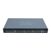
Describes ports and LEDs located on the front panel of the switch.
Use these ports to connect network devices to the switch.
Small form-factor pluggable ports for modules and linking switches.
Explains the status indicators on the front panel of the switch.
Procedure to reset the switch to factory default settings.
Location of power and console ports on the rear of the switch.
Procedures to reboot or reset the switch to factory defaults.
Steps to troubleshoot connection issues and possible causes.
Links to Cisco support communities and resources.
Links to Cisco product documentation and safety information.
Links to partner resources and test results.
| Model | SG500-52P |
|---|---|
| Ports | 52 |
| PoE Ports | 48 |
| PoE+ | Yes |
| Switching Capacity | 104 Gbps |
| Layer | Layer 3 |
| Power over Ethernet (PoE) | Yes |
| Rack Mountable | Yes |
| VLAN Support | Yes |
| Manageable | Yes |
| Jumbo Frame Support | Yes |
| Power Supply | Internal |
| Dimensions | 440 x 44 x 350 mm |
| MAC Address Table Size | 16K entries |
| Operating Temperature | 0°C to 50°C |
| Storage Temperature | -20 to 70°C (-4 to 158°F) |
| Relative Humidity | 10% to 90%, non-condensing |