Step 3 Pull out the width-adjustment slider that is at the opposite end of the CMA assembly until it matches the width of your
rack.
Step 4 Slide the CMA tab that is at the end of the width-adjustment slider onto the end of the stationary slide rail that is attached
to the rack post. Slide the tab over the end of the rail until it clicks and locks.
Step 5 Open the hinged flap at the top of each plastic cable guide and route your cables through the cable guides as desired.
Reversing the Cable Management Arm (Optional)
Step 1 Rotate the entire CMA assembly 180 degrees, left-to-right. The plastic cable guides must remain pointing upward.
Step 2 Flip the tabs at the ends of the CMA arms so that they point toward the rear of the server.
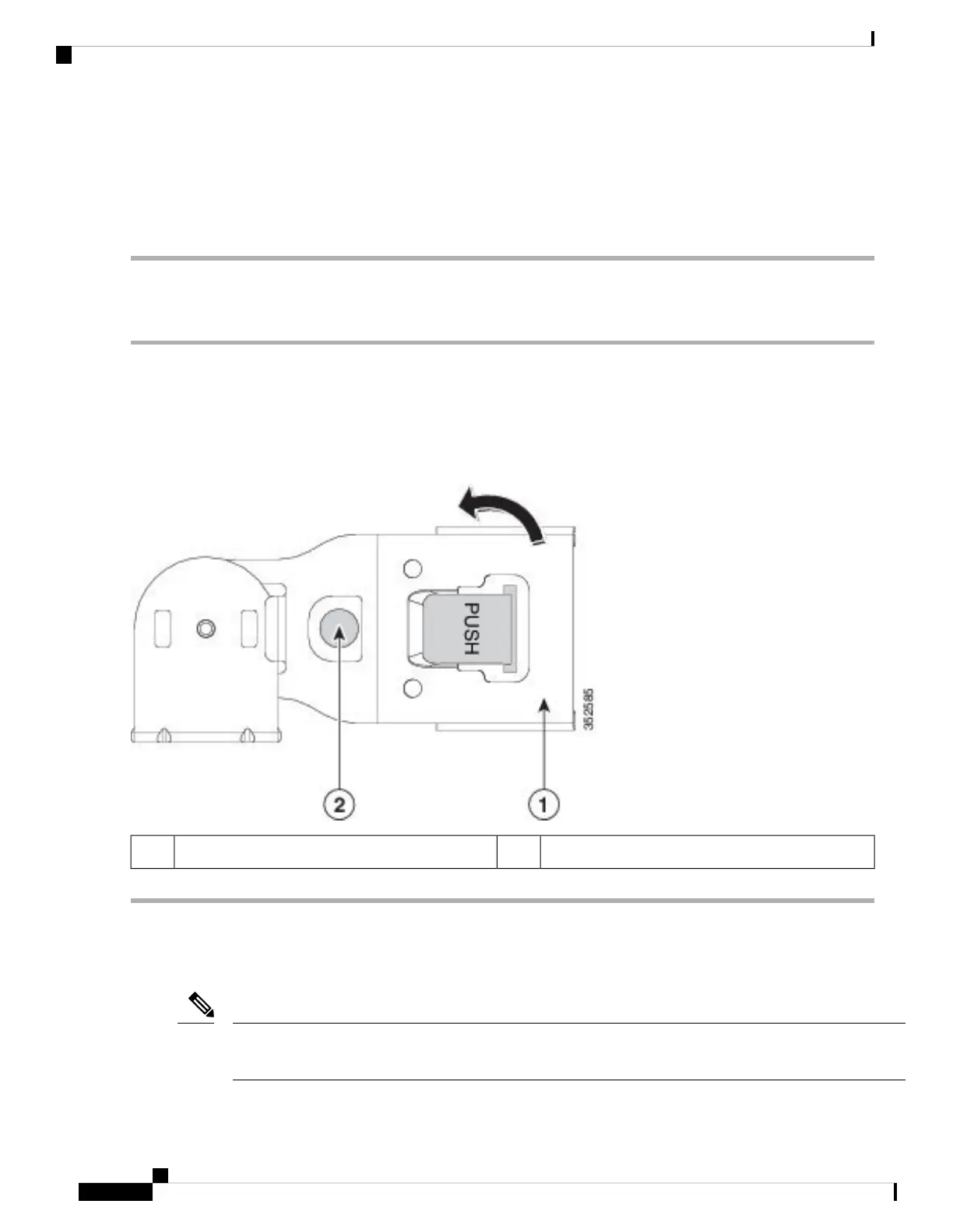
Step 3 Pivot the tab that is at the end of the width-adjustment slider. Depress and hold the metal button on the outside of the tab
and pivot the tab 180 degrees so that it points toward the rear of the server.
Figure 5: Reversing the CMA
Metal button on outside of tab2CMA tab on end of width-adjustment slider1
Initial Server Setup
This section describes how to power on the server, assign an IP address, and connect to server management
when using the server in standalone mode.
Note
Installing the Server
10
Installing the Server
Reversing the Cable Management Arm (Optional)
 Loading...