3-2
Cisco UCS C220 M4 Server Installation and Service Guide
OL-32473-01
Chapter 3 Maintaining the Server
Status LEDs and Buttons
Status LEDs and Buttons
This section describes the location and meaning of LEDs and buttons and includes the following topics
• Front Panel LEDs, page 3-2
• Rear Panel LEDs and Buttons, page 3-5
• Internal Diagnostic LEDs, page 3-7
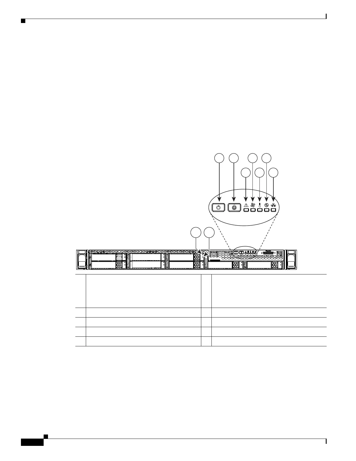
Front Panel LEDs
Figure 3-1 shows the front panel LEDs. Table 3-1 defines the LED states.
Figure 3-1 Front Panel LEDs
1 Hard drive fault LED
Note: NVMe PCIe SSDs drive tray LEDs
have slightly different behavior. See Table 3-1
for the LED states.
6 Fan status LED
2 Hard drive activity LED 7 Temperature status LED
3 Power button/power status LED 8 Power supply status LED
4 Identification button/LED 9 Network link activity LED
5 System status LED
353088
975
3 4 6 8
BAY 02
BAY 01 BAY 03
BAY 04
BAY 05
BAY 06
BAY 08
BAY 07
21
 Loading...


