19-inch EIA brackets419-inch EIA brackets3
3. Use the screws provided with the rack to install the chassis in the rack. For both the 19-inch EIA brackets
and the 23-inch SBC brackets, start the lower pair of screws first, and rest the brackets on the lower screws
while you insert the upper pair of screws.
The screw slots in the brackets are spaced to line up with every second pair of screw holes in the rack. When
the correct screw holes are used, the small, threaded holes in the brackets line up with unused screw holes in
the rack. If the small holes do not line up with the rack holes, you must raise or lower the brackets to the next
rack hole.
Tip
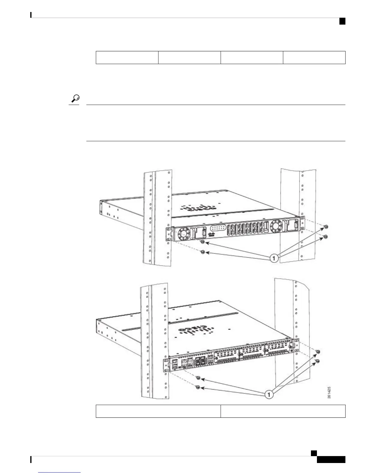
The following image shows a typical installation with back mounting
Figure 5: Bracket Installation for Back Mounting
Mounting Screws (4)1
Cisco VG400 Voice Gateway Hardware Installation Guide
23
Installing the Cisco VG400 Voice Gateway
Mount Cisco VG400 Voice Gateway Chassis in Rack

 Loading...


