CBM-910 User’s Manual
CITIZEN
15
5.3 Description of Input/ Output Signals
(1) Input signal
* DATA 1………..8 bit parallel signal (positive logic)
* DATA 2………..8 bit parallel signal (positive logic)
* DATA 3………..8 bit parallel signal (positive logic)
* DATA 4………..8 bit parallel signal (positive logic)
* DATA 5………..8 bit parallel signal (positive logic)
* DATA 6………..8 bit parallel signal (positive logic)
* DATA 7………..8 bit parallel signal (positive logic)
* DATA 8………..8 bit parallel signal (positive logic)
* STB……………Strobe signal for reading out data (negative logic)
* RESET………...Signal for resetting the entire unit (negative logic 4ms or more)
(2) Output signal
* ACK…………..8 bit data signal for requesting data. ACK is issued at the end of the BUSY signal (negative logic)
* BUSY…………Signal indicating the printer is busy. Input new data when the signal is in “LOW” condition.
(positive logic)
* HI-LEVEL……Connected to Vcc via 3.3 kΩ resistance.
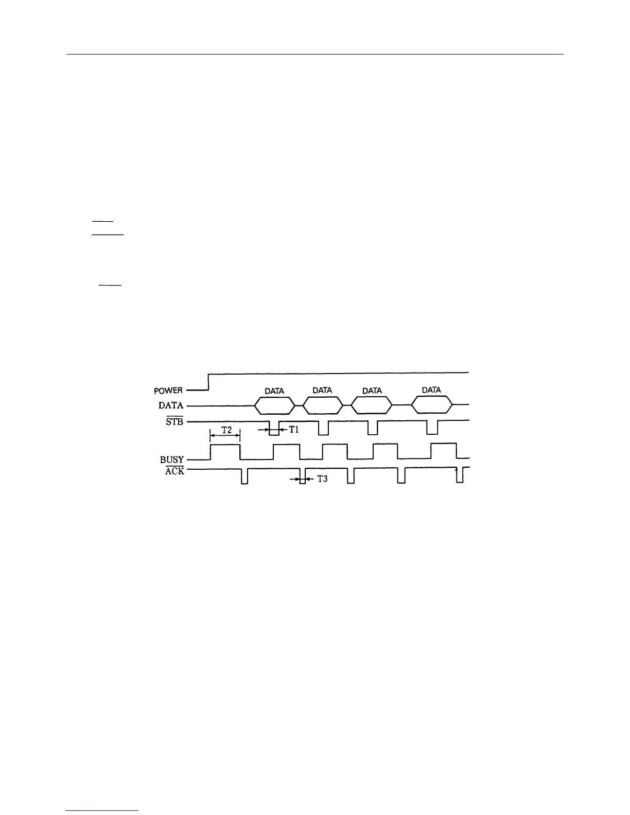
(3) Timing chart
T1 2.7µs MIN
T2 500mS MIN (When power is supplied)
T3 10µs TYP
 Loading...