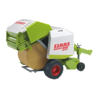
298 332.0 - RHB ROLLANT 250 / 250 RC
0.1.1
Contents
CONTENTS
Contents ................................................................................ 0.1.1
1. General information
General .................................................................................. 1.1.1
Introduction ...................................................................... 1.1.1
Introduction to the CLAAS REPAIR MANUAL ................. 1.1.2
Key to symbols ................................................................ 1.1.3
Safety rules ............................................................................ 1.2.1
Important information ....................................................... 1.2.1
Identification of warning and danger signs ...................... 1.2.2
Correct use of the round baler ......................................... 1.2.2
General safety and accident prevention regulations ....... 1.2.2
Leaving the round baler ................................................... 1.2.2
Service ............................................................................. 1.2.3
Basic rule ......................................................................... 1.2.3
General repair information ..................................................... 1.3.1
Reason of damage .......................................................... 1.3.1
Spare parts ...................................................................... 1.3.1
Transmission ................................................................... 1.3.1
Tensioning the steel roller chains .................................... 1.3.1
Taper ring fasteners ........................................................ 1.3.1
Self-locking bolts ............................................................. 1.3.1
Liquid locking compound ................................................. 1.3.1
Correct installation of lock collar bearings ....................... 1.3.2
Correct installation of adapter sleeve bearings ................ 1.3.2
Ferrule fittings on hydraulic lines ..................................... 1.3.2
Progressive ring fittings on hydraulic lines ....................... 1.3.3
Taper fittings on hydraulic lines ....................................... 1.3.3
Welding ............................................................................ 1.3.3
Some advice for speedy and correct repair work: ........... 1.3.4
Tightening torques ................................................................. 1.4.1
Bolts ................................................................................. 1.4.1
Hydraulic screw fittings .................................................... 1.4.2
Specifications ......................................................................... 1.5.1
Lubricants chart ............................................................... 1.5.1
2. Drives
Universal Drive Shaft ............................................................. 2.1.1
Disassembling the universal drive shaft half
(tractor side) .................................................................... 2.1.1
Assembling the universal drive shaft half on the
tractor side ....................................................................... 2.1.4
Disassembling the universal drive shaft half
(machine side) ................................................................. 2.1.7
Assembling the universal drive shaft half
(machine side) ................................................................. 2.1.8
Disassembling the cam-type cut-out clutch ................... 2.1.11
Assembling the cam-type cut-out clutch ........................ 2.1.12
Angle drive, intermediate drive .............................................. 2.2.1
Removing the angle drive ................................................ 2.2.1
Disassembling the angle drive ......................................... 2.2.2
Assembling the angle drive ............................................. 2.2.7
Installing the angle drive ................................................ 2.2.14
Drive Diagram ........................................................................ 2.3.1
Drives, left-hand side ....................................................... 2.3.1
Drives, right-hand side ..................................................... 2.3.2
Drive chains, left-hand side ................................................... 2.4.1
Removing the roller drive (top) ........................................ 2.4.1
Installing and tensioning the roller drive (top) ................. 2.4.3
Removing the roller drive (front) ...................................... 2.4.6
Installing the roller drive (front) ........................................ 2.4.7
Removing the cutting rotor/feed rotor drive ..................... 2.4.9
Installing and adjusting the cutting rotor/
feed rotor drive .............................................................. 2.4.10
Removing the drive of rollers 1, 2 and 16 ..................... 2.4.11
Installing and adjusting the drive of rollers 1, 2 and 16 . 2.4.12
Removing the pick-up drive (left) .................................. 2.4.13
Installing the pick-up drive (left) .................................... 2.4.14
Removing the intermediate drive of pick-up drive
on rotor machines ......................................................... 2.4.17
Installing the intermediate drive of pick-up drive
on rotor machines ......................................................... 2.4.18
Drive chains/drive belts on right-hand side ........................... 2.5.1
Removing the feed auger drive (right) ............................. 2.5.1
Installing the feed auger drive (right) ............................... 2.5.1
Removing the tailgate roller drive .................................... 2.5.2
Installing the tailgate roller drive ...................................... 2.5.3
Removing and disassembling the tying drive .................. 2.5.6
Assembling and mounting the tying drive ....................... 2.5.8
Removing and installing the net wrapping/
twine wrapping drives .................................................... 2.5.11
3. Pick-up / Rollers
Pick-up lift .............................................................................. 3.1.1
Removing the hydraulic pick-up lift ................................. 3.1.1
Installing the hydraulic pick-up lift ................................... 3.1.2
Pick-up .................................................................................. 3.2.1
Removing the gauge wheel ............................................. 3.2.1
Disassembling the gauge wheel ..................................... 3.2.1
Gauge wheel, disassembled ........................................... 3.2.3
Assembling the gauge wheel .......................................... 3.2.4
Removing the short crop baffle ....................................... 3.2.5
Installing the short crop baffle ......................................... 3.2.6
Replacing the spring tine ................................................. 3.2.6
Removing the pick-up and auger .................................... 3.2.6
Pick-up and auger, disassembled ................................... 3.2.7
Installing the pick-up and auger ...................................... 3.2.8
Replacing the left-hand drive shaft lock collar bearing .... 3.2.9
Replacing the right-hand drive shaft lock collar bearing 3.2.10
Removing the pick-up ................................................... 3.2.11
Mounting the pick-up ..................................................... 3.2.12
Removing the cam track ............................................... 3.2.13
Removing the guide rollers ........................................... 3.2.15
Removing the tine carrier .............................................. 3.2.16
Removing the drive shaft .............................................. 3.2.16
Pick-up, disassembled .................................................. 3.2.17
Mounting the tine carrier ............................................... 3.2.19
Mounting the cam track ................................................. 3.2.19
Cutting/feed unit .................................................................... 3.3.1
Removing the cutting rotor/feed rotor .............................. 3.3.1
Disassembling the cutting rotor/feed rotor ...................... 3.3.2
Find manuals at http://best-manuals.com/search?&s=CLA-2983320

 Loading...