EasyManuals Logo

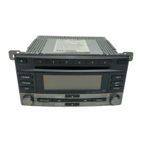
Clarion AX523R Service Manual

Clarion AX523R
17 pages
To Next Page IconTo Next Page
To Previous Page IconTo Previous Page
Page #2 background imageLoading...
Page #2 background image
¥
@
To
engineers
in
charge
of
repair
or
inspection
of
our
products.
Before
repair
or
inspection,make
sure
to
follow
the
instructions
so
that
customers
and
Engineers
in
charge
of
repair
or
inspection
can
avoid
suffering
any
risk
or
injury.
1.
Use
specified
parts.
The
system
uses
parts
with
special
safety
features
against
fire
and
voltage.
Use
only
parts
with
equiva-
lent
characteristics
when
replacing
them.
The
use
of
unspecified
parts
shall
be
regarded
as
remodeling
for
which
we
shall
not
be
liable.
The
onus
of
product
liability
(PL)
shall
not
be
our
responsibility
in
cases
where
an
accident
or
failure
is
as
a
result
of
unspecified
parts
being
used.
Place
the
parts
and
wiring
back
in
their
Original
positions
after
replacement
or
re-wiring.
For
proper
circuit
construction,
use
of
insulation
tubes,
bonding,
gaps
to
PWB,
etc,
is
involved.
The
wiring
connection
and
routing
to
the
PWB
are
specially
planned
using
clamps
to
keep
away
from
heated
and
high
voltage
parts.
Ensure
that
they
are
placed
back
in
their
original
positions
after
repair
or
inspection.
If
extended
damage
is
caused
due
to
negligence
during
repair,
the
legal
responsibility
shall
be
with
the
repairing
company.
Check
for
safety
after
repair.
Check
that
the
screws,
parts
and
wires
are
put
back
securely
in
their
original
position
after
repair.
Ensure
for
safety
reasons
there
is
no
possibility
of
secondary
problems
around
the
repaired
spots.
If
extended
damage
is
caused
due
to
negligence
of
.fepair,
the
legal
responsibility
shall
be
with
the
re-
pairing
company.
Caution
in
removal
and
making
wiring
connec-
tion
to
theparts
for
the
automobile.
Disconnect
the
battery
terminal
after
turning
the
ig-
nition
key
off.
If
wrong
wiring
connections
are
made
with
the
battery
connected,
a
short
circuit
and/or
fire
may
occur.
If
extensive
damage
is
caused
due
to
negligence
of
repair,
the
legal
responsibility
shall
be
with
the
repairing
company.
Cautions
regarding
chips.
Do
not
reuse
removed
chips
even
when
no
abnor-
mality
is
observed
in
their
appearance.
Always
re-
place
them
with
new
ones.
(The
chip
parts
include
resistors,
capacitors,
diodes,
transistors,
etc).
The
ms
Adjustment
‘Tape
Speed
negative
pole
of
tantalum
capacitors
is
highly
sus-
ceptible
to
heat,
so
use
special
care
when
replacing
them
and
check
the
operation
afterwards.
6.
Cautions
in
handling
flexible
PWB.
Before
working
with
a
soldering
iron,
make
sure
that
the
iron
tip
temperature
is
around
270°C.
Take
care
not
to
apply
the
iron
tip
repeatedly
(more
than
three
times)
to
the
same
patterns.
Also
take
care
not
to
ap-
ply
the
tip
with
force.
7.
Turn
the
unit
OFF
during
disassembly
and
parts
replacement.
Recheck
all
work
before
you
apply
power
to
the
unit.
i
Notes
of
ISO
Connector
1.
For
VW
and
Audi
vehicles,
change
the
position
of
fuse
installation
as
shown
on
the
diagram.
(Figure
1)
The
position
of
fuse
for
other
vehicles
The
position
of
fuse
for
VW
and
Audi
vehicles
Main
unit
side
{SO
connector
Figure
1
2.
The
lead
include
with
the
unit
must
be
connected
to
specified
position
of
the
vehicle's
|SO
connector
in
order
to
use
the
“triggered
audio
mute
for
cellular
telephones”
function.
(Figure
2)
Main
unit
side
!SO
connector
Vahiglevaiie
ISO
connector
i
Connect
the
included
brown
lead
to
the
connector's
“PHONE
MUTE"position.
Terminal
side
Connect
to
cellular
phone
mute
lead.
Fasten
using
insulating
tape,etc.,
to
prevent
short-circuits
at
the
connection.
Figure
2
Procedure
RDS
S-Meter
modulation
OFF.
seconds.(Test
Mode)
.
Input
the
98.1MHz/30dB
(400Hz,
75kHz
DEV,AF88%)
signal
and
2.
Adjust
VR
on
top
of
the
tuner
so
that
the
output
level
at
the
TP
(S-
Meter)
on
main
PWB
is
2.4+0.1V
.
Input
the
98.1MHz/30dBy/400Hz(Main90%+Pilot10%)signal
2.
Turn
on
the
power
switch
and
press
the
AF
button
and
2
3.
Adjust
the
reading
of
LCD
indicator
to
[30----00]
3.020.2V
by
VR1.
Procedure
-SSG
-Multiplex
Signal
Generator
-Millivoltmeter
1.
Insert
a
wow
speed
tape,
and
adjust
speed-VR
of
main
motor
so
that
a
reading
of
wow
flutter
meter
is
3000----3090Hz
-2-
-Wow
speed
Tape
-Wow
flutter
meter

Other manuals for Clarion AX523R

Questions and Answers:

Question and Answer IconNeed help?

Do you have a question about the Clarion AX523R and is the answer not in the manual?

Clarion AX523R Specifications

General IconGeneral
BrandClarion
ModelAX523R
CategoryCar Receiver
LanguageEnglish

Related product manuals