E
Elizabeth WarrenAug 15, 2025
What to do if Clarion ADB341MP Car Receiver has microcomputer reset failure?
- JJoe GlassAug 15, 2025
If your Clarion Car Receiver experiences a microcomputer reset failure, check pin R781, R794 for a reset issue.
What to do if Clarion ADB341MP Car Receiver has microcomputer reset failure?
If your Clarion Car Receiver experiences a microcomputer reset failure, check pin R781, R794 for a reset issue.
What to do if my Clarion Car Receiver has no operation?
If your Clarion Car Receiver is not working, there could be several reasons. It could be due to a power input failure, in which case you should check the power input circuit L601, J214, and J215. Another cause could be a POWER ON circuit failure; inspect Q601, Q602 for 5V output normal failure.
Why Clarion ADB341MP Car Receiver has no operation because of no 5V output?
If your Clarion Car Receiver isn't operating because of a missing 5V output, check Q703 PIN 2 for microcomputer IC701 failure.
What to do if Clarion Car Receiver has no operation because of no B/U power output?
If your Clarion Car Receiver is not working because there is no B/U power output, check Q621 collector for 14V output failure.
What to do if Clarion ADB341MP has no operation because of no function operated?
If your Clarion Car Receiver isn't operating because no function is working, inspect Q602 base for microcomputer IC701.
What to do if Clarion ADB341MP has no operation because of 0V output failure?
If your Clarion Car Receiver is not working because of a 0V output failure, check IC501 PIN 22 for power amp IC failure.
Why Clarion Car Receiver has no operation because of 8.6V output failure?
If your Clarion Car Receiver isn't operating because of an 8.6V output failure, inspect Q612 emitter for AUDIO 8V input power failure.
What to do if Clarion ADB341MP has no operation because of 14V output failure?
If your Clarion Car Receiver is not working because of a 14V output failure, check Q363 collector for cassette 5V input power failure.
Why Clarion ADB341MP Car Receiver has no operation because of 6V output failure?
If your Clarion Car Receiver isn't operating because of a 6V output failure, inspect IC631 OUT for CD6V input power failure.
Overview of electrical parts for the unit.
Visual breakdown of components and their part numbers.
Critical safety and procedural guidelines for repair.
Troubleshooting steps for general operational issues.
Troubleshooting steps specific to CD playback issues.
Troubleshooting steps specific to tape playback issues.
Explanation of CD error codes and their solutions.
Exploded view and parts list for the main unit.
List of electrical components for the Main PWB(B1).
List of electrical components for the Sub PWB(B2).
List of electrical components for the Display PWB(B3).
List of electrical components for the Servo PWB(B4).
Circuit diagram for Main PWB(B1), part 1 of 3.
Circuit diagram for Main PWB(B1), part 2 of 3.
Circuit diagram for Main PWB(B1), part 3 of 3.
Printed wiring layout for Main PWB(B1), part 1 of 2.
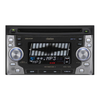
| Type | Car Receiver |
|---|---|
| Brand | Clarion |
| Model | ADB341MP |
| DIN Size | 1 DIN |
| RMS Power Bandwidth | 20 Hz - 20 kHz |
| Tuner | AM/FM |
| Supported Media | CD, MP3, WMA |
| CD Player | Yes |
| MP3 Playback | Yes |
| WMA Playback | Yes |
| Bluetooth | No |
| Display | LCD |
| CD Signal-to-Noise | 90 dB |
| Detachable Face | Yes |
| Max Power Output | 50W x 4 |
| RMS Power Output | 22W x 4 |
| Peak Output | 50 Watts |
| Preamp Outputs | 2 |