DB345MP/DB346MPDB345MP/DB346MP
DB345MP/DB346MPDB345MP/DB346MP
DB345MP/DB346MP
- 17 -- 17 -
- 17 -- 17 -
- 17 -
N
B
----
----
--
--
(Copper Side)
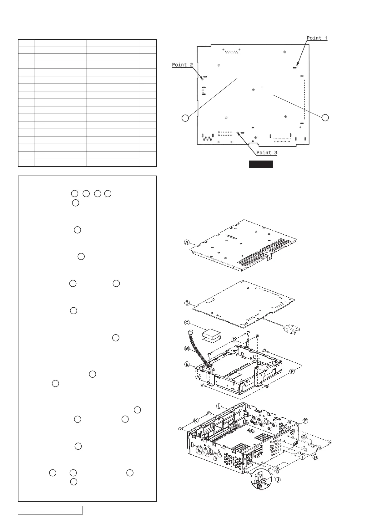
Figure 1
REMOVING MAIN PWB FOR REPAIR
See from bottom side
A 311-1848-00 LOWER CASE 1
B 039-2423-00 MAIN PWB 1
C 816-2640-60 FLAT WIRE 1
D 731-3005-81 TAPTIGHT 3
E 929-0290-80 MECHANISM 1
F 313-1872-05 HEAT SINK 1
G 731-3012-80 TAPTIGHT 2
H 714-3006-81 MACHINE SCREW 2
I 731-3008-80 TAPTIGHT 4
J 714-2012-81 MACHINE SCREW 1
K 714-2606-87 MACHINE SCREW 2
L 370-6101-00 INNER ES 1
M 854-4569-60 EXTENSION LEAD 1
N 076-0349-04 CONNECTOR 1
P 714-2604-81 MC SCREW 3
Q 335-0833-01 CABLE TIE 1
No Part Number Part Name QTY
Step 1
Remove all screw , , , , from Heat Sink
cut off the cable tie .
Step 2
Remove Heat Sink .
Step 3
Remove Lower Case .
Step 4
Remove all screw , from Inner ES .
Step 5
Remove Inner ES .
Step 6
Unsolder 3 points on the Main PWB ,
(Figure 1).
Step 7
Unplug the extension lead from the
connector .
Step 8
After unsoldering Main PWB, remove flat wire
between Main PWB , and Mechanism .
Step 9
Remove Main PWB for repairing.
Step 10
Unscrew and from the upper case ,
if the mechanism needs replacement.
Q
F
K L
L
M
N
G
H I J
B
E
P
B
A
C
B
E
D D

 Loading...