14
English
M255
To protect the system, this unit has been equipped with self diagnostic functions. If a fault
arises, a warning is issued by various error displays. Follow the corrective measures and
remove the fault.
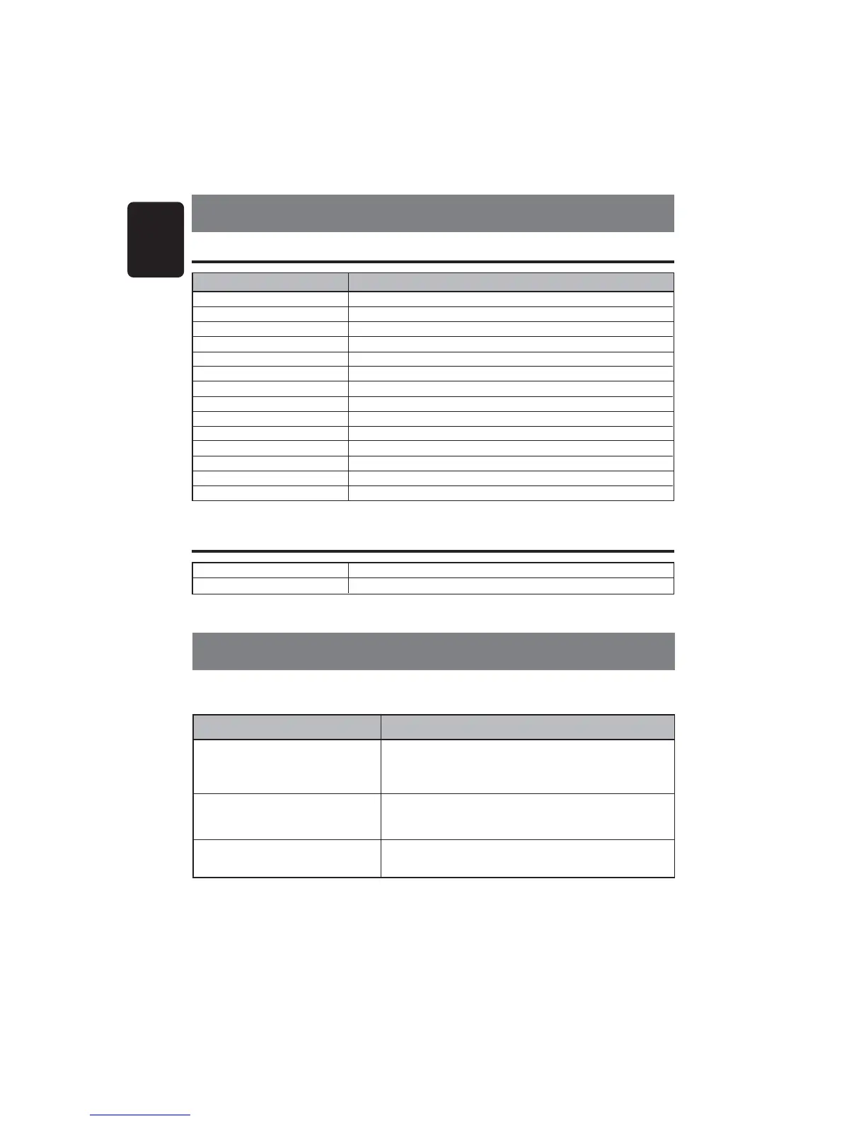
10.ERROR DISPLAYS
ER 2
Error Display Corrective Measure
This error display indicates that a fault has arisen in the
mechanism of the source unit
(
for example, the disc cannot be
ejected
)
.
ÆÆ
ÆÆ
Æ Check the source unit.
This error display indicates that the pickup focus is off because
of a scratched disc or some other factor during source unit play.
ÆÆ
ÆÆ
Æ Check the compact disc.
This indicates that the CD’s TOC
(
table of contents
)
cannot be
read, for example because the selected disc is upside-down.
ER 3
ER 6
+12VDC Constant Power Source/Memory
+12VDC Switch Lead/Accessory
Ground
Power Antenna Turn-on
Dimmer
Amplifier Remote Turn-on
Right Front Speaker
(+)
Right Front Speaker
(-)
Left Front Speaker
(+)
Left Front Speaker
(-)
Right Rear Speaker
(+)
Right Rear Speaker
(-)
Left Rear Speaker
(+)
Left Rear Speaker
(-)
Yellow
Red
Black
Blue
Orange/White
Blue/White
Grey
Grey/Black
White
White/Black
Purple
Purple/Black
Green
Green/Black
Wire Color Function
Yellow
Red
Black
Blue
Orange/White
Blue/White
Grey
Grey/Black
White
White/Black
Purple
Purple/Black
Green
Green/Black
Red
White
Right Rear Line Level Output
(
Full Range
)
Left Rear Line Level Output
(
Full Range
)
∗ Note: All wire functions may not be available on the head unit.
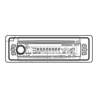
Head Unit Harness Wire Connections
9.WIRE CONNECTIONS
RCA Connections