- 1 -- 1 -
- 1 -- 1 -
- 1 -
M335/M235M335/M235
M335/M235M335/M235
M335/M235
Source unit 1
DCP Case 335-5734-22 1
Mounting bracket 300-7742-20 1
Outer Escutcheon
(PE-2587B-A) 370-6041-01 1
Outer Escutcheon
(PE-2587B-B) 370-6041-02 1
Extension Lead 854-6391-60 1
Part’s bag 1
Removal key 331-2497-20 2
PE-2587B-A PE-2587B-BPE-2587B-A PE-2587B-B
PE-2587B-A PE-2587B-BPE-2587B-A PE-2587B-B
PE-2587B-A PE-2587B-B
FEATURES
NOTE
1. We cannot supply PWB with component parts in
principle. When a circuit on PWB has failure, please
repair it by component parts base. Parts which are
not mentioned in service manual are not
supplied.
SeSe
SeSe
Se
rvrv
rvrv
rv
ice Manualice Manual
ice Manualice Manual
ice Manual
Published by Clarion (Malaysia)
298-6026-00 JUNE 2003P
Printed In Malaysia
Clarion ( Malaysia) Sdn. Bhd.Clarion ( Malaysia) Sdn. Bhd.
Clarion ( Malaysia) Sdn. Bhd.Clarion ( Malaysia) Sdn. Bhd.
Clarion ( Malaysia) Sdn. Bhd.
Phase 3, Free Trade Zone One, 11900 Bayan Lepas, Penang, Malaysia
Tel: (60) 4-6439-106, Fax: (60) 4-6439-108
Clarion Co. Ltd.Clarion Co. Ltd.
Clarion Co. Ltd.Clarion Co. Ltd.
Clarion Co. Ltd.
Export Division : 50 Kamitoda, Toda-shi, Saitama 335-8511 Japan
AM/FM Marine CD PlayerAM/FM Marine CD Player
AM/FM Marine CD PlayerAM/FM Marine CD Player
AM/FM Marine CD Player
ModelModel
ModelModel
Model
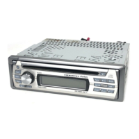
M335M335
M335M335
M335
(Model : PE-2587B-A: For all countries)
ModelModel
ModelModel
Model
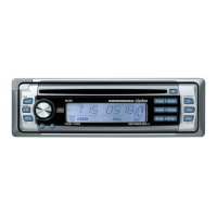
M235M235
M235M235
M235
(Model : PE-2587B-B: For all countries)
(Model: M335)
(Model: M235)
COMPONENTS
Radio sectionRadio section
Radio sectionRadio section
Radio section
Model: PE-2587B-A Model: PE-2587B-A
Model: PE-2587B-A Model: PE-2587B-A
Model: PE-2587B-A (with wire remote control)
Model: PE-2587B-B Model: PE-2587B-B
Model: PE-2587B-B Model: PE-2587B-B
Model: PE-2587B-B (without remote control)
Tuning system: PLL synthesizer tuner
Receiving frequencies:FM 87.9 to 107.9MHz
(0.20 MHz steps)
AM 530 to 1,710kHz (10 kHz steps)
CD player sectionCD player section
CD player sectionCD player section
CD player section
System: Compact disc audio system
Usable disc: Compact disc
Frequency response: 10Hz to 20kHz (+1dB/-1dB)
Signal to Noise ratio: 100dB (1kHz) IHF-A
Dynamic range: 95dB (1kHz)
Distortion: 0.01%
GeneralGeneral
GeneralGeneral
General
Max. Power Output: 50W x 4
Line Output: 1.7V (with CD 1kHz, 10k ohm)
Bass Control Action: +14dB/-14dB (30Hz)
Treble Control Action: +14dB/-14dB (10 kHz)
Power supply voltage: DC 14.4V (10.8 to 15.6V allowable)
negative ground
Current consumption: Less than 15A
Speaker impedance: 4 ohm (4 ohm to 8 ohm allowable)
Dimensions (mm): 178 (W) x 50 (H) x 152 (D)mm
Weight: 1.1kg
SPECIFICATIONS
Specification and design are subject to change without notice for
further improvement.
M335M335
M335M335
M335
Conformally Coated Microprocesor
Plays CD-R & CD-RWs
Z-Enhancer
Rotary Volume Control
Input for Marine Wired Remote Control
White Positive LCD with White Buttons
Detachable Faceplate
2 Channel RCA Line Level Output
200 Watt (50W x 4)
Tuner with 18 FM/6 AM Preset
Magna Bass EX
Screen Saver
Aluminium Face Plate
M235M235
M235M235
M235
Conformally Coated Microprocesor
Detachable Faceplate
Plays CD-R & CD-RWs
2 Channel RCA Line Level Output
200 Watt (50W x 4)
Z-Enhancer
Magna Bass EX
Tuner with 18 FM/6 AM Preset
Rotary Volume Control
White Psitive LCD with White Buttons
Screen Saver