PP-2898H-C,F
- 4 -
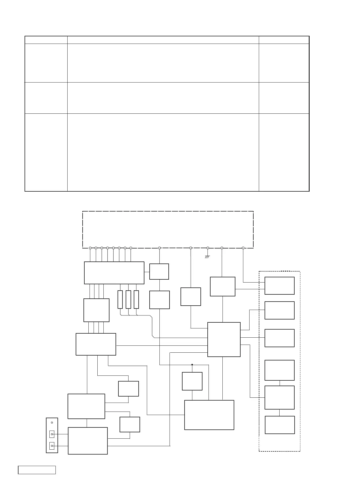
MAIN
AM/FM-TUNER
POWER-IC
TDA7560
ANT101
BL101
1CD
MECHANISM
STBY
BEEP
BACK UP
ACC
ILL-
ILL+
GND
IC402
IC501 - 505
NJM2060V
EQ-AMP
IC301
E-VOL
LC75412
LCD-DRIVER
IC601
VR601
MAIN VOL.
S615
CD-EJECT
ILL
IC201
AUDIO-CPU
LC723663
ILL
CONT.
FILLTER
MUTE
OUT
FM
CD
FL
FR
RL
RR
DISP
KEY-
MATRICS
FR LH(+)
J401(POWER/SP)
FR LH(-)
RR LH(+)
RR LH(-)
FR RH(+)
FR RH(-)
RR RH(+)
RR RH(-)
Q414,416
S601 - 614
LC75853
LCD601
ACC-DET
Q415
CD-8V
Q410
CD-5V
Q408
SW PWB
FM-DIVER
IC101
AM
AM-NC
IC103
AF-OUT
AF-AMP
IC102
N-IN
SUB
ADJUSTMENT
Item Procedure
Measuring instrument
Clock accuracy
1. Connect the Choronometer to TP218.
2. Connect the B/U and ACC line, and Turn on the ACC switch.
3. LCD display change Ver.---, While holding the buttons of MENU,M1,M5 and
POWER.
4. Adjust TC201 so that an output of TP218 becomes 0.0 +0.2/-0.0Sec./day.
SSG
Milli-volt meter
Oscilloscope
Choronometer
FM noise
convergence
1. Input the 98.1MHz/55dBu(1kHz 22.5kHz Div.) SSG signal.
2. Set the output to 0dBm(1V)by main volume.
3. Adjust VR102 so that the output level is -18+3/-3dB down when the output of
SSG is set to -20dBu.
SSG
Milli-volt meter
FM DIV.
1. Connect the SSG to Main antenna (Red) side.
2. Set the minimum VR101.
3. Input the 98.1MHz/1kHz 22.5kHz(30%) Div. SSG signal.
4. Input the 26dBu SSG signal and adjust VR101 so that an output of TP101(DIV-
ADJ) becomes High from Low.
5. Confirm that TP101(DIV-ADJ) becomes Low from High within about three sec-
onds of input the 22dBu SSG signal.
6. Confirm that TP101(DIV-ADJ) becomes 10.0V from 2.0V within about one sec-
ond of input the 30dBu SSG signal.
7. Confirm that TP101(DIV-ADJ) is as follows 1.0V within five seconds of input the
20dBu SSG signal.
BLOCK DIAGRAM
Main section