MAINTENANCE
ALWAYS disconnnect from the power supply
before carrying out any maintenance
After use
1. Accumulated dust and chips should be
removed from inside the bandsaw. Open the
Wheel Cover and use a brush or vacuum
cleaner at the end of every work session.
2. ALWAYS Lower the Blade Guide Block and
Guard Assembly to its lowest position and lock
it in place.
3. ALWAYS slacken off blade tension.
Periodically
1. Apply a coat of wax paste to the table surface
which will allow the wood stock to glide across
it smoothly and effortlessly.
2. Inspect electric cables to ensure they are not
cracked or damaged in any way. Damaged
cables should be renewed immediately.
3. Inspect the blade for damaged teeth. If any
are broken, the blade should be renewed.
BLADE RENEWAL
1. Disconnect the mains cable from the supply.
2. Slacken off blade tension fully, using the
adjuster knob on top of the machine.
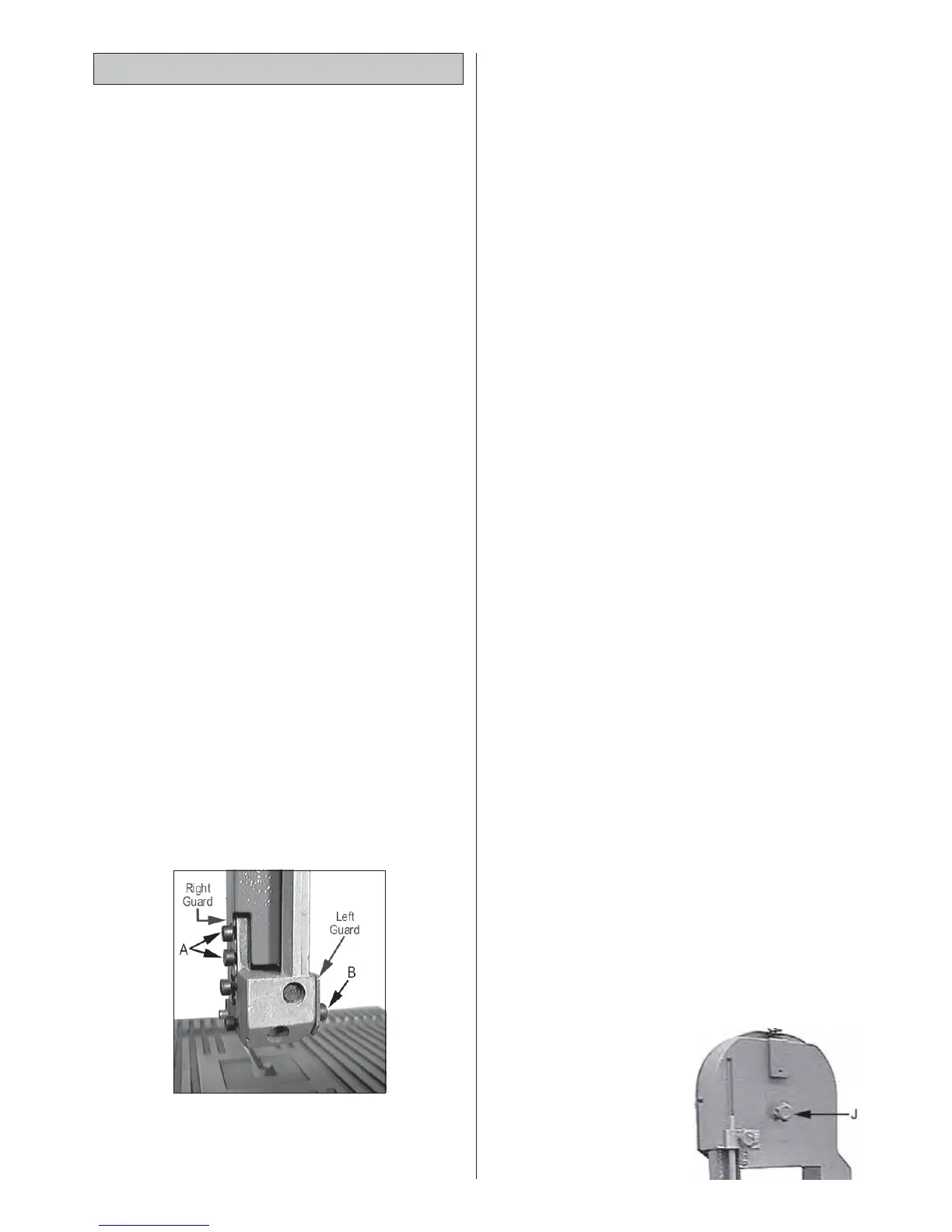
3. Remove both halves of the Upper Blade
Guard by removing the screws at B, Fig. 10 ,
sufficient for the left half of the guard may be
removed, and slackening off screws A, fig 10,
so that the right half may be removed.
4. Remove the Table Insert and the Clamping
Screw, within the table slot, then remove the
table.
5. Open the Wheel Cover using a screwdriver
on each of the two knob centre screws
6. Ease the blade off the upper and lower
wheels, taking care that the blade does not
‘spring’ as this could cause serious injury. It is
advisable to wear proper clothing, i.e.
industrial gloves, long sleeves and goggles.
7. Refer to Figs. 12 and 13, and using the Hex.
wrench provided, slacken off the screws ‘A’
and ‘G’. This frees the two Blade Support
Bearings, the upper one of which is shown at
‘E’.
Move the bearing ‘E’, and the Lower Guide
Block (H), backwards as far as possible.
8. Slacken off the screws shown at ‘B’ and ‘D’.
This frees the Blade Guides shown at ‘C1 and
C2’....move them away from each other to
provide a gap..
9. Replace the new blade - over the lower
wheel first.
NOTE: It may be necessary to slacken of the brush
mountings in the lower left corner of the wheel housing
in order to manoeuvre the blade between brush and
wheel rim.
Ease the blade over the upper wheel and
through the Blade Guide Block assemblies,
ensuring the teeth point down towards the
table.
10. Try as far as possible to align the blade so that
it runs as near central on the wheels as
possible, then apply tension by turning the
Blade Tension Adjuster Knob clockwise until
the blade feels firm on its run between the
two wheels, but do not overtighten.
11. Readjust the brush if previously moved, or if
not, check to ensure it is brushing firmly up
against the wheel.
NOTE: The brush is responsible for bringing the wheels,
and hence the blade, to a quick stop when the
machine is switched off.
12. Carry out all adjustments, i.e. Blade tracking
and Blade Guide Bearings, as follows:
A. Blade Tracking
NOTE: Removal of the upper blade guards and table
not only simplifies the blade removal process but also
gives easy access to the various components which
will subsequently require adjusting.
Fig. 11
10
Fig.10
It is important that the
blade runs centrally
about the upper and
lower wheels. Note that
the upper wheel carries
a rubber tyre which has
a convex outer surface.
It is important therefore
to ensure the blade runs
 Loading...