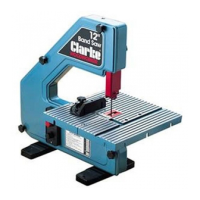
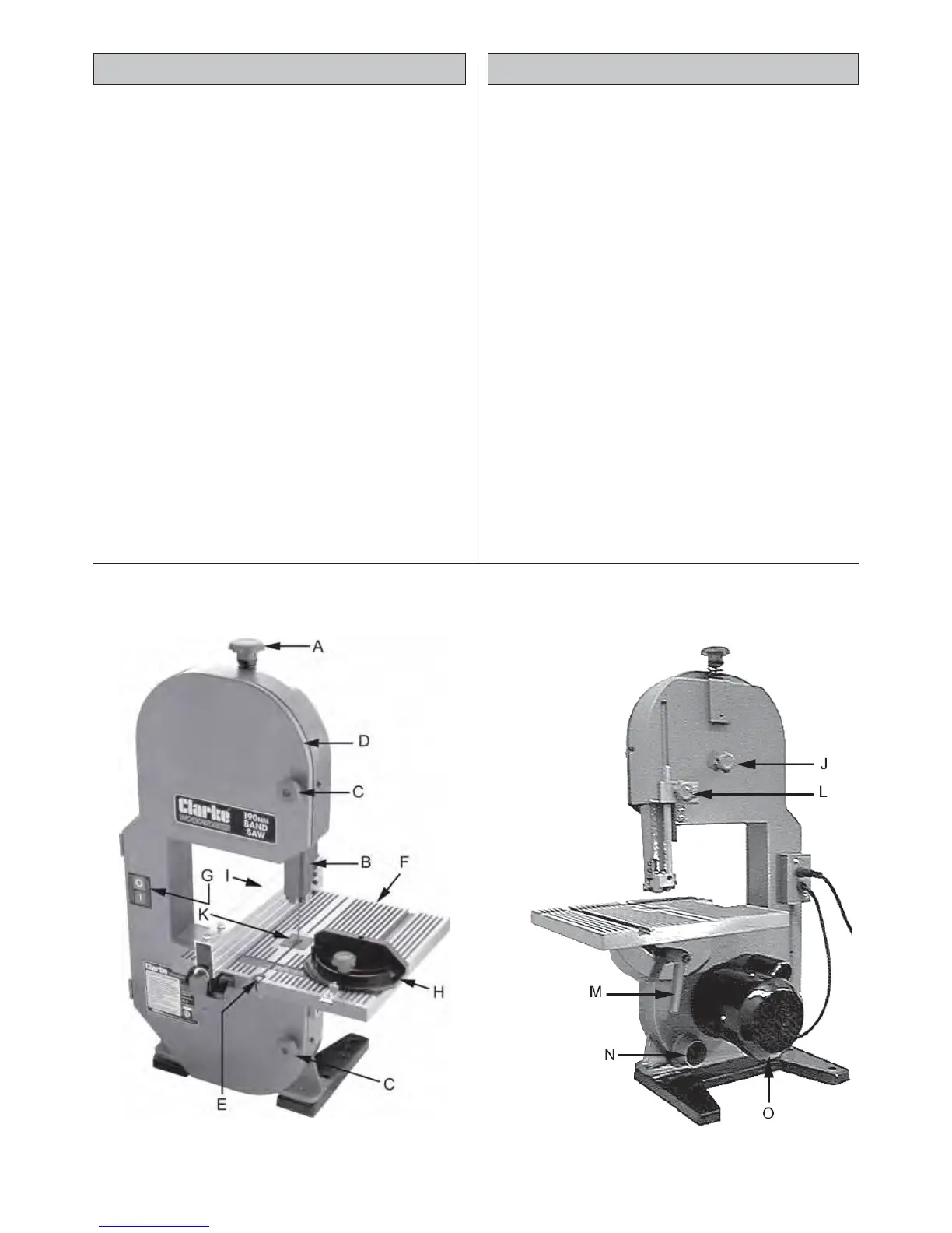
PRINCIPAL PARTS
(Ref. Fig. 1)
A Blade Tension Adjuster Knob
B Upper Guide Block and Blade Guard
Assembly.
C Wheel Cover Knobs
D Wheel Cover
E Table Clamping Screw
F Table
G ON/OFF Switch
H Mitre Gauge
I Parallel (Rip) Fence
J Blade Tracking Adjuster
K Table Insert
L Upper Blade Guard Securing Knob
M Table Securing Handle
N Dust Extraction Outlet
O Motor
UNPACKING
Unpack the shipping carton and lay out all the
items so that they may be clearly identified as
follows:
• Main Frame Assembly complete
• Table Assembly
• Mitre Gauge Assembly
• Parallel Fence Assembly
• 2 x Hex. Wrenches.
• 1 x Table Clamping Screw, with handle
Check to ensure that no damage was suffered
in transit, and that all parts are accounted for.
You should contact your CLARKE dealer
immediately, should there be any damage or
deficiency
Fig. 1
6
 Loading...