17
(ii) Ensuring Blade is Square
a. Slacken screw ‘C’ Fig.18 so that the carrier may be moved laterally, i.e.
pivoted about screw ‘C’.
b. Place an engineers square (arrowed in Fig.19) on the bed, as near as
possible to the guide carrier, and bring up to the blade as shown in Fig.19.
c. Turn the guide carrier until the blade is perfectly in line with the engineers
square, then tighten the screw ‘C’, ensuring the roller ‘D’ is lightly touching
the top edge of the blade.
d. Repeat the process with the other blade guide carrier.
e. Check the alignment at the middle of the run, then bring the carriers together
and check again. Make any adjustment necessary to either carrier to ensure the
blade is at right angles to the bed, then ensure all nuts and screws are tight.
C. Blade Tracking Adjustment
This adjustment is carried out at the factory
and it should not normally require
readjustment. If the blade is thrown, first try
a new blade as this should normally cure
the problem. If the new blade does not
track correctly however, adjust the tracking
as follows:
1. Ensure the plug is disconnected and the
Arm in the vertical position. Adjust the
blade so that only moderate tension is
applied.
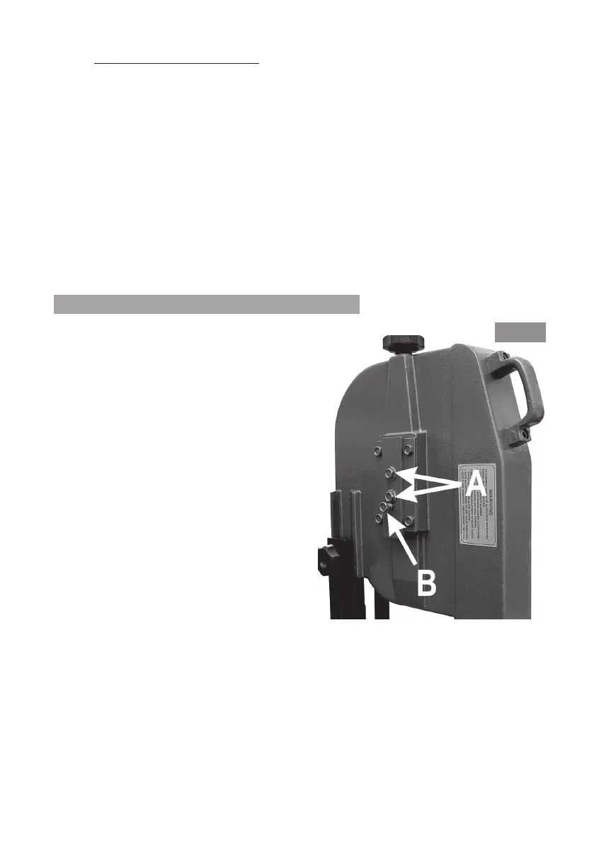
2. Slacken the two Hex socket head
screws, shown at ‘A’ fig.20, by one turn.
3. If the blade runs off the rim of the pulley
wheel, turn the Hex. socket head screw,
shown at ‘B’ fig.20 CLOCKWISE, slowly.
The blade will move back towards the
lip at the back of the pulley.
If it rubs up against the lip, a harsh
scraping sound will become apparent.
Fig. 20
Turn the screw ANTICLOCKWISE until the sound disappears then tighten screws
‘A’.
4. Continue to monitor the action of the blade for a few moments to ensure it
runs neatly. If necessary, slacken off the two screws ‘A’ and adjust using screw
‘B’ accordingly.