MS-702 TWO-CHANNEL MAIN STATION
3-1
MAINTENANCE
INTRODUCTION
This chapter provides maintenance information, including a block diagram and troubleshooting tips.
Caution:These servicing instructions are for use by qualified personnel only. To reduce the risk of electrical shock, do not
perform any servicing other than that contained in the operating instructions unless you are qualified to do so.
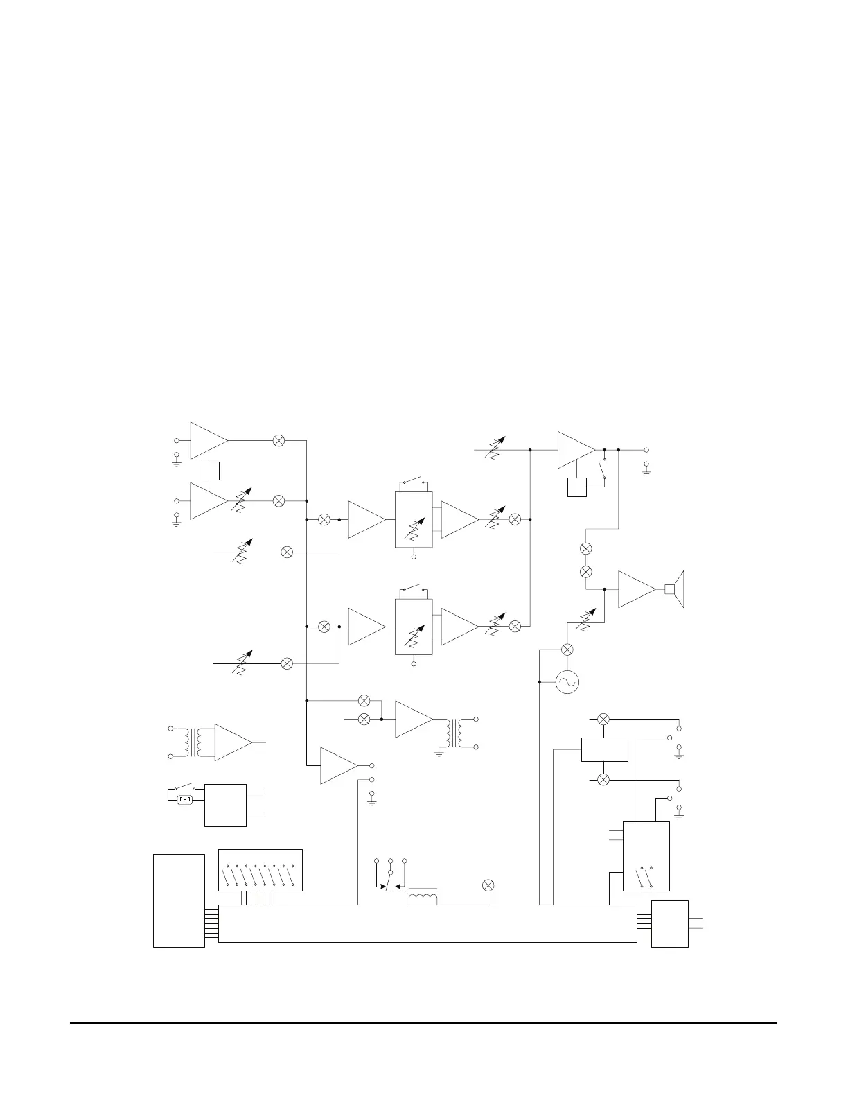
MS-702 BLOCK DIAGRAM
The following is a block diagram of the MS-702:
Figure 3-6: Block diagram of the MS-702
Headset
Mic
Panel Mic
Gain
Panel
Mic
Jack
XLR4
Main
Pgm
Program
Level A
3
2
SA
Output
Hot Mic /
IFB Out
Main
Pgm
Listen
A
Program
Level
XLR4
Headset
Headset
Limiter
Line
Length
Sidetone
Null
Intercom
Line A
Program
Level B
Listen
B
Line
Length
Sidetone
Null
Intercom
Line B
Main
Pgm
3
2
Main
Pgm
Main
Pgm
Power A
3
1
2
Channel A
XLRs (3)
Power B
3
1
2
Channel B
XLRs (3)
Power
Control uP
+30VDC
+30VDC
Call
Signal
Send &
Receive
System Logic
Front Panel
Switches,
Buttons, &
Indicators
Annc Rly
Control
To All
Switches
MS-702
RMK Link
A
B
Intercom
Lines
A
B
Intercom
Lines
Main
Pgm
Alert Tone
Generator
Alert Tone
Level
Call Alert
Tone
Intercom
Line Linking
&
Termination
Spkr
On/Off
Mute
Mic
Limiter
Option Switches
Switching
Power
Supply
+30VDC
IEC Power
Inlet
On/Off
+5VDC
3