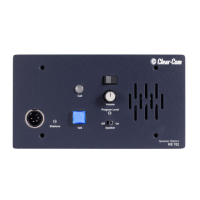
KB-702/KB-702GM TWO-CHANNEL SPEAKER STATIONS
1-7
Option modules are installed, this jumper is not used. In TW operation, the
call signal always originates on channel A. In 4-Wire operation, the call
signal is not used.
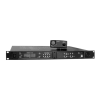
16. Intercom Line Connection: The KB-702 contains a 5-terminal plug-on
connector for intercom line connection. This connector is intended to be
unplugged from the circuit board when connecting the intercom line, and
then plugged back on when the wiring is completed. The connections for
each pin are visible on the circuit board when the connector is unplugged.
The pinout of this connector is as follows:
Pin 1 --- (NC)
Pin 2 --- Channel A Audio
Pin 3 --- Channel B Audio
Pin 4 --- Power
Pin 5 --- Ground (Shield)
Figure 1-4: One-Channel Cable Wiring
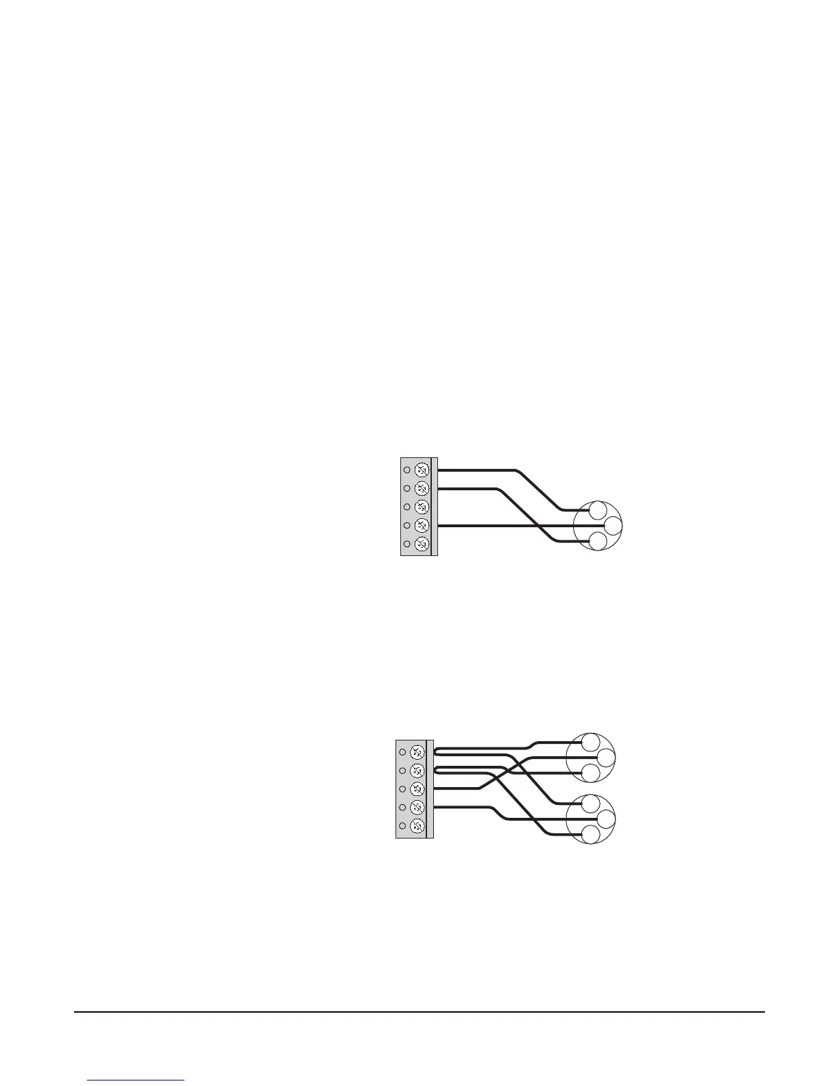
Figure 1-5: Two-Channel Cable Wiring
17. Program Input: A 3-terminal plug-on connector provides the program input
to the station. Program is fed to the headset and speaker. The level to the
One Channel
Cable Wiring:
KB-702 Intercom
Connector
XLR
Connector
Channel A
Pin 1
Pin 5
1
3
2
Two Channel
Cable Wiring
KB-702 Intercom
Connector
XLR
Connectors
Channel A
Channel B
Pin 1
Pin 5
1
3
2
1
3
2