M
Maria MitchellAug 12, 2025
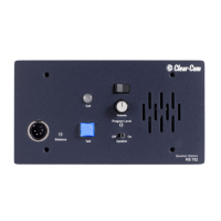
Why am I getting system feedback (acoustical) in my Clear-Com KB-702GM Intercom System?
- XxrobinsonAug 12, 2025
Acoustical feedback in your Clear-Com Intercom System can occur if the intercom level control at one or more stations is set too high. Try adjusting the level. It can also happen if the sidetone null control isn't adjusted correctly; in this case, adjust the sidetone null control. Also, ensure the channel is properly terminated by setting the main station or power supply termination switch for that channel to the on position. If you're using an unconnected channel, set option switch #1 to the on or closed position to link both channel switch positions to the same intercom line. Finally, avoid using headset extension cords as they are not recommended.