26 Party Line Link (A+B) LED: This green LED is lit when the Party Line Link (A+B) switch is
ON, to provide a visual indication that party line Channels A and B are linked together.
27 Tone Alert LED: This green LED lights when the Tone Alert function is enabled. Tone Alert
is an audible indication that a Call signal is active. Toggle the Tone Alert function ON or OFF
using the Tone Alert button.
28 Power LED: This green LED lights when the MS-232 is receiving AC power and the power
switch on the rear panel is turned on.
29 Short LEDs: There is one red LED for Channel A and one for Channel B. These LEDs light
when the MS-232 senses a short or overload on the associated channel. When the fault is re-
moved, the MS-232 will automatically reset and the LED will go out.
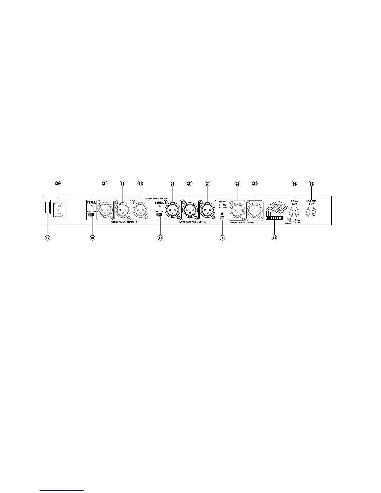
Rear Panel
The controls and connectors found on the MS-232 rear panel are shown in the following figure and
briefly described by the following text. The numbers in the left column refer to Figure 2.
Figure 2 - Rear Panel
4 Tone Alert Volume Control: This control adjusts the volume of the Tone Alert sound. This
is normally adjusted when the system is set up and there should be no need to adjust it in nor-
mal operation.
15 Option Switches: Eight Option switches are provided on the rear panel. They should be
configured when the system is set up, but are not changed in normal operation. The default
position of the switches is in the OFF (up) position. The function of each switch is as follows:
1 MOM TALK A: Setting the Momentary Talk A switch to the ON position will disable the
latching function of the Channel A Talk button. In this mode, the Talk button must always
be held in continuously while the operator is talking on Channel A.
2 MOM TALK B: Setting the Momentary Talk B switch to the ON position will disable the
latching function of the Channel B Talk button. In this mode, the Talk button must always
be held in continuously while the operator is talking on Channel B.
3 CALL ON TALK A: If the Call On Talk A switch is set to the ON position, a Call signal will
be placed on Channel A whenever the Talk function is activated. This can be used to acti-
vate any Call activated functions available on other stations.
4 CALL ON TALK B: If the Call On Talk B switch is set to the ON position, a Call signal will
be placed on Channel B whenever the Talk function is activated. This can be used to acti-
vate any Call activated functions available on other stations.
5 INTRPT ANNC: If the Interrupt Announce switch is set to the ON position, pressing the
Announce button will disconnect the microphone from the intercom line(s). This will allow
announcements to be made without being heard over the intercom channels.
6 INTRPT EXT IFB: When the Hot Mic output is connected to Clear-Com's IFB System and
the Interrupt External IFB switch is set to the ON position, pressing a key on the IFB
Clear-Com MS-232 Two-Channel Main Station
6