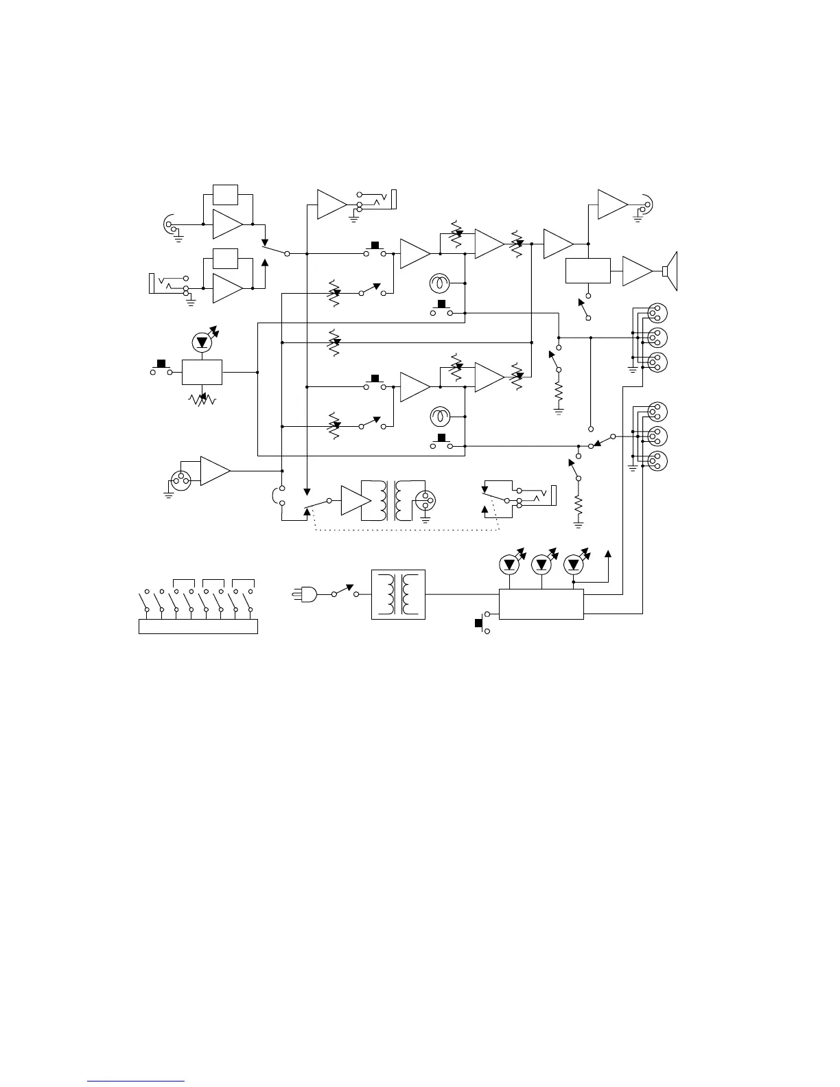
MS-232 Block Diagram
The following is a block diagram of the MS-232:
Figure 3 - MS-232 Block Diagram
TROUBLESHOOTING
Problem: System does not operate. Green POWER LED is not illuminated and no
SHORT LED's are illuminated
Cause 1: No AC power to the MS-232.
Solution 1: Make sure the power switch on the rear panel is turned ON. Check the AC connec-
tion and cable. Plug into a dependable AC source.
Cause 2: The MS-232 has an internal power supply failure.
Solution 2: Unit requires servicing.
Problem: System does not operate when power switch is turned on. Green POWER
LED and red SHORT LED wink
Cause: Direct short on the intercom channel indicated by the red Short LED.
Solution: Remove the intercom line cables one at a time from that channel until the faulty
line is located. Once the short is removed, the MS-232 will reset automatically and
power will come back up within several seconds. Check for shorts between pins 1
and 2 or improper cable wiring.
Clear-Com MS-232 Two-Channel Main Station
9
EQ/
LIM
EQ/
LIM
Headset
Select
Headset
Mic
Panel Mic
Hot Mic
Out
Announce
Announce
Output
Talk
Int. On/Off
Program
Level A
Sidetone
Call
Light
Call
Send
Channel A
Listen
Talk
Int. On/Off
Program
Level B
Sidetone
Call
Light
Call
Send
Channel B
Listen
Green
Alert
Volume
Tone
Alert
Speaker
Dip/Mute
Speaker
On/Off
Program
Feed on
Announce
Option
Balanced
Program
Input
Announce
Relay
Switching Power
Supply
Short Circuit Protection
Ch. A Ch. B
Red
Short
Green
OK
Remote
Mic Kill
Program
Level
Term.
Sw.
Term.
Sw.
A+B
Link
Ch. A
Output
Ch. B
Output
Speaker
Headset
Output
Station
Power
Control Logic
Interrupt
Annc. IFB
Call on
Talk
Talk
Momentary
Long
Line
A B A B A B
Option Switches
Power
On/Off