FOR-22 4-WIRE INTERFACE
2-2
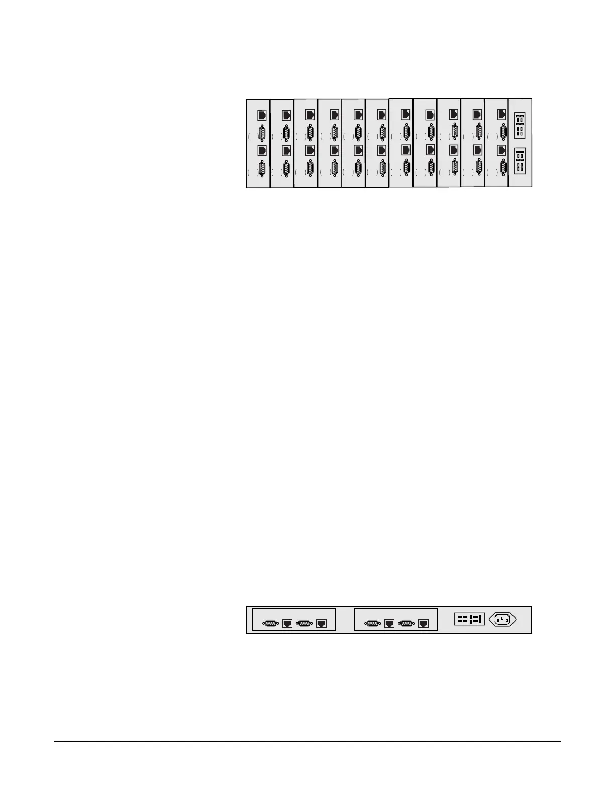
Figure 1: IMF-3 Interface Frame Rear Panel
Note: The IMF-3 frame has an individual rear panel for each interface. All interfaces
use the same rear panel; however the use of the rear-panel connectors will vary with
the type of interface.
Each interface features indicators and controls that must be accessible to
operators, so put the interface module frame(s) in a convenient location. Usually
interface module frames are located near the matrix frame, but they can be
located farther away. The maximum distance between the matrix frame and the
interface frame is 500 feet (150 meters).
Each Eclipse frame contains its own power supplies and does not supply any
power for interfaces. A separate power supply (PSU-101) is only necessary for
interfaces mounted in IMF-3 frames. If redundant power supply pairs are used
for interfaces, mount them together.
It is required that you leave an extra rack unit (1.75 in. or 44.45 mm) above and
below each external power supply unit. This allows for needed cooling for larger
system loads.
IMF-102 Interface Module Frame
The IMF-102 interface frame has slots for two interface modules in one rack unit
(1 RU) of a standard Electronics Industry Association 19-inch wide (48.26 cm)
rack.
It has an internal power supply and a connector for a redundant power supply.
The IMF-102 requires 90 to 250 VAC with a maximum dissipation of 20 watts.
Its rear input/output connector panel has two RJ-45 connectors and two DB-9
connectors for the two interface modules. Figure 2 illustrates the rear panel of an
IMF-102 interface frame, with two installed rear-panel assemblies.
Figure 2: IMF-102 Interface Frame Rear Panel
For more information on the IMF-102 interface frame, refer to its manual in the
Eclipse manual set.
CH. A
Matrix
CH. A
I/O
CH. B
Matrix
CH. B
I/O
PHONE
LINE A
PHONE
LINE B
CH. A
Matrix
CH. A
I/O
CH. B
Matrix
CH. B
I/O
PHONE
LINE A
PHONE
LINE B
CH. A
Matrix
CH. A
I/O
CH. B
Matrix
CH. B
I/O
PHONE
LINE A
PHONE
LINE B
CH. A
Matrix
CH. A
I/O
CH. B
Matrix
CH. B
I/O
PHONE
LINE A
PHONE
LINE B
CH. A
Matrix
CH. A
I/O
CH. B
Matrix
CH. B
I/O
PHONE
LINE A
PHONE
LINE B
CH. A
Matrix
CH. A
I/O
CH. B
Matrix
CH. B
I/O
PHONE
LINE A
PHONE
LINE B
CH. A
Matrix
CH. A
I/O
CH. B
Matrix
CH. B
I/O
PHONE
LINE A
PHONE
LINE B
CH. A
Matrix
CH. A
I/O
CH. B
Matrix
CH. B
I/O
PHONE
LINE A
PHONE
LINE B
CH. A
Matrix
CH. A
I/O
CH. B
Matrix
CH. B
I/O
PHONE
LINE A
PHONE
LINE B
CH. A
Matrix
CH. A
I/O
CH. B
Matrix
CH. B
I/O
PHONE
LINE A
PHONE
LINE B
CH. A
Matrix
CH. A
I/O
CH. B
Matrix
CH. B
I/O
PHONE
LINE A
PHONE
LINE B
POWER SUPPLY #1
POWER SUPPLY #2
CH.A
Marix
CH.A
I/O
CH.B
Matrix
CH.B
I/O
CH.A
Marix
CH.A
I/O
CH.B
Matrix
CH.B
I/O