Adjustments
4-6
750-297
Profire E/LNE Series Manual
of change. The closer the rod to the hub of the lever, the less distance it will travel.Increasing the lever length on the
damper, metering unit and valve(s) decreases flow rate.
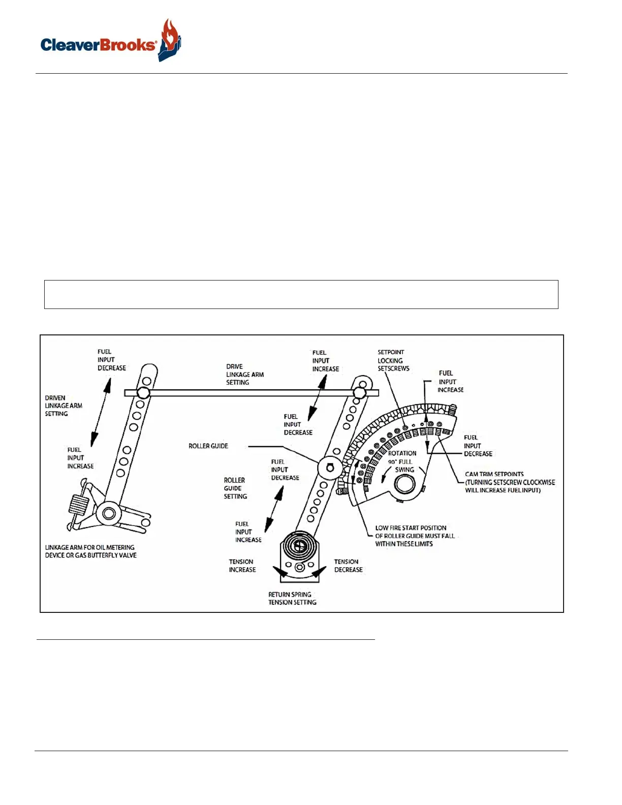
4.7 — Cam Trim Adjustment
After low and high fire adjustments are complete, final adjustment is made with the cam assembly to obtain a good air/
fuel ratio throughout the entire firing range.The input of combustion air is fixed at any given point in the modulating
cycle. The fuel input may be varied to obtain correct flue gas readings. The adjustment is made to the metering cam by
means of the 14 adjusting screws which are turned in (clockwise from the hex-socket end) to increase the flow of fuel,
and out (counterclockwise from the hex-socket end) to decrease it. A 3/32” hex key is required. It will be necessary to
cut off the short end of a hex key to approximately 3/8” to adjust the first two socket head setscrews at the low fire
position. Take a combustion analysis at various points of the cam profile. Adjustment can be made without cycling the
burner, then operate the automatic modulating cycle to assure satisfactory results. Tighten the locking setscrews.
FIGURE 4-1. Cam Trim Adjustment
4.8 — Parallel Positioning Adjustment
For parallel positioning systems refer to the control manufacturer's documentation and to the accompanying wiring
diagram for information on adjusting the system. In a properly tuned parallel positioning system the independent
NOTE: It is essential that the cam spring, cam follower bearing wheel, and cam follower arm at the pivot point be greased
sparingly every month to ensure smooth operation of the cam assembly. Regular automotive bearing grease should be used.