6
SERVICE INSTRUCTIONS
REASSEMBLY
— GENERAL
IMPORTANT: During reassembly of the complete tool, the
gear case should be tightened to the handle to 20 ft. lbs.
(27Nm). Wrenches can be ordered for performing this task
on page 7.
All parts should be washed in a solvent and inspected for
damage or wear. Particular attention should be given to all
bearings, gears, gear pins, and rotor blades as failure of
these parts could cause damage to more expensive parts.
Rotor blades should be replaced if they measure less than
1/8" (3.175mm) on either end. Rotor blades should be sized
in length to .003"/.004" (.0762mm/.1016mm) shorter than
the cylinder.
Inspect and replace any "O"-rings or seals that show signs
of wear of deterioration. All gears, gear pins, and open
bearings should receive a generous amount of NLGI 2-EP
grease during reassembly. Reassembly of all of the various
subassemblies is in reverse order of disassembly: however,
the following paragraphs list some of the more important
reassembly procedures.
CLUTCH REASSEMBLY
Clecomatic Clutch:
During reassembly of the clutch, all parts should receive a
thin coating of 10W machine oil. In addition, the ball retainer
203573, should receive a generous amount of NLGI 2-EP
grease. When installing the dowl pin 617226, the tapered
end goes into the clutch cam first. The trip slide 203612, goes
into the clutch cam cupped-end first. All parts installed into
the clutch spindle and clutch cam 203572, should be checked
for smooth operation before complete assembly of the
clutch.
MOTOR REASSEMBLY
Install the rear rotor bearing, into the rear bearing plate
203506. If using new parts, check for burrs or nicks. After
installing new cylinder pins, check for burrs around pins.
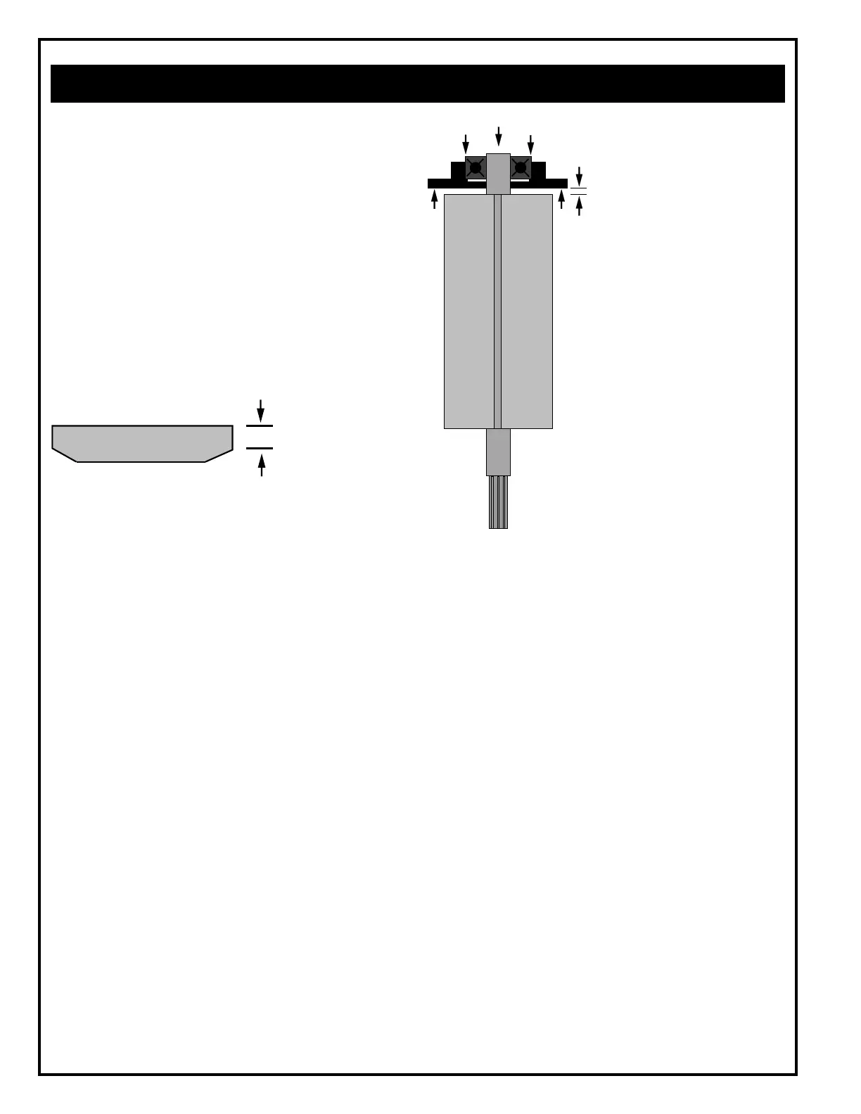
Press the bearing plate assembly (press on the bearing's
inner race) onto the rear rotor shaft until there is approxi-
mately .0015" (.038mm) clearance between the rear bearing
plate and rotor.
Replace blade if less
than 1/8"(3.175mm)
on either end.
.0015" (.038mm)
Clearance