EasyManua.ls Logo

Clemco 1028 - User Manual

Clemco 1028
13 pages
Print Icon
To Next Page IconTo Next Page
Loading...
WARNING
Do not proceed with
these instructions*
until you have READ
the orange cover of
this MANUAL and YOU
UNDERSTAND its
contents.
These WARNINGS are
included for the health
and safety of the
operator and those in
the immediate vicinity.
*If you are using a Clemco Distributor
Maintenance and Part Guide, refer to
the orange warnings insert preceding
the Index before continuing with the
enclosed instructions.
Electronic files include a Preface
containing the same important
information as the orange cover.
SINGLE CHAMBER BLAST MACHINE
MODELS 1028 AND 1042
O. M. 04124
DATE OF ISSUE: 01/15/77
REVISION: K, 07/13
© 2013 CLEMCO INDUSTRIES CORP.
One Cable Car Dr.
Washington, MO 63090
Phone (636) 239-4300
F
ax (800) 726-7559
Email: info@clemcoindustries.com
www.clemcoindustries.com
Question and Answer IconNeed help?

Do you have a question about the Clemco 1028 and is the answer not in the manual?

Summary

Introduction and Core Safety

Scope (1.1)

Details setup, operation, maintenance, troubleshooting, and replacement for blast machines.

Safety Alerts (1.2)

Explains safety alert signal words (Danger, Warning, Caution) and their meanings.

Machine Description (1.3)

Describes primary components and ASME standards for blast machines.

Abrasive, Setup, and Operation Basics

Abrasive Selection (1.4)

Covers selection of blasting abrasive, safety data sheets, and types.

Initial Set-Up Procedures (2.0)

Outlines the initial setup procedures for the blast machine and accessories.

Transporting and Moving (3.1)

Provides critical safety warnings and instructions for moving the blast machine.

Machine Setup and Preparation (3.2)

Covers connecting air lines, hoses, and preparing the machine for operation.

Detailed Operation and Safety

Manual Blasting (3.3)

Explains the procedure for operating the blast machine manually.

Remote Control Blasting (3.4)

Details the steps for operating the blast machine using remote controls.

Blasting Attire and Safety (3.4.2)

Specifies essential protective gear and safety measures for operators.

Abrasive Flow, Loading, and Shutdown

Covers adjusting abrasive flow, loading, and safe shutdown procedures.

Maintenance, Service, and Troubleshooting

Preventive Maintenance (4.0)

Outlines regular maintenance schedules and procedures for the blast machine.

Service Maintenance (5.0)

Covers essential service and repair procedures, emphasizing safety.

Troubleshooting Common Issues (6.0)

Identifies common problems and their solutions for the blast machine.

Replacement Parts

Accessories (7.1)

Lists accessories like remote controls, filters, and covers with stock numbers.

Machine Parts (7.2, 7.3)

Details replacement parts for metering valves, components, and accessories.

Overview

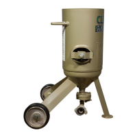
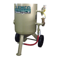
This document outlines the setup, operation, maintenance, troubleshooting, and replacement parts for Clemco Models 1028 and 1042 single chamber blast machines. These machines are designed for abrasive blasting applications and are available in two capacities: 0.5 cu ft (Model 1028) and 1.0 cu ft (Model 1042). They can be configured for either remote-controlled operation (with a pneumatically operated control handle at the nozzle) or manually-controlled operation (with simple ball valves at the inlet and outlet).

Function Description:

The Clemco blast machines are pressure vessels manufactured to American Society of Mechanical Engineers (ASME) standards, Section VII, Div. 1, and carry National Board certification. They are used for abrasive blasting, where compressed air propels abrasive media through a nozzle to clean or prepare surfaces. The process involves loading abrasive into the machine, pressurizing the vessel with compressed air, and then controlling the flow of abrasive and air through a metering valve to the blast hose and nozzle. Remote controls (TLR-50 Remote Controls and RLX Control Handle) are required by OSHA for blast operators controlling the nozzle, ensuring safety by providing a fail-to-safe feature. Manually-controlled machines are only permitted when the nozzle is fixed and separated from personnel.

Important Technical Specifications:

  • Models: 1028 (0.5 cu ft capacity) and 1042 (1.0 cu ft capacity).
  • Maximum Working Pressure: 125 psi (pounds per square inch). Exceeding this pressure can cause rupture and serious injury or death.
  • ASME Certification: Manufactured to ASME Section VII, Div. 1 standards and National Board certified. Owners are responsible for maintaining vessel integrity, which may include regular inspection and hydrostatic testing.
  • Nozzle Orifice Sizes: Common sizes include 1/8" (No. 2), 3/16" (No. 3), and 1/4" (No. 4). The document provides a table detailing air (cfm), abrasive (lbs/hr), and compressor (hp) requirements for these nozzle sizes at various pressures (50-100 psi).
  • Compressor Requirements: Depend on nozzle orifice size and blasting pressure. The table in Figure 2 shows consumption rates for new nozzles, noting that consumption increases as nozzles wear (70% to 80% more air).
  • Abrasive Compatibility: Compatible with slag abrasives, silicon carbide, aluminum oxide, garnet, and glass bead. Steel or iron abrasive is generally not suitable for the metering valve due to potential jamming. Sand containing crystalline (free) silica should not be used due to respiratory hazards. Lightweight abrasives like plastic media may require a machine with a 60° conical bottom for continuous flow.
  • Remote Control Systems: TLR-50 Remote Controls (Manual Stock No. 03358) and RLX Control Handle (Manual Stock No. 10574) are separate components.

Usage Features:

  • Safety Alerts: The manual uses ANSI Z535.4-1998 signal words (CAUTION, WARNING, DANGER) to highlight potential hazards.
  • Pre-Operation Checks: Emphasizes reading and understanding the manual's safety warnings, ensuring proper training and qualification of operators, and wearing appropriate personal protective equipment (PPE), including NIOSH-approved respirators, eye, face, and hearing protection.
  • Transporting: Machines must be emptied of abrasive before lifting or hoisting. They should never be hoisted by the handle or piping. When on a pallet or transport vehicle, the machine must be securely attached. Empty machines can be moved manually on level surfaces by pushing forward.
  • Set-Up: Compressor should be located upwind or away from blasting to prevent contaminated air intake. Connect a 3/4" ID or larger air line. Isolation valves are recommended for lines supplying other pneumatic tools. Ensure coupling gaskets are in good condition and all hose connections are secured with safety lock pins or wires to prevent accidental disconnection under pressure.
  • Abrasive Loading: Abrasive is poured into the concave head, ideally with an optional screen to prevent foreign objects from entering. The abrasive level should be kept below the pop-up valve to prevent it from being forced up when pressurized.
  • Abrasive Metering: Abrasive flow is adjusted with the metering handle, starting from a closed (fully clockwise) position and increasing counterclockwise in small increments. Optimum flow depends on abrasive type, size, and blast pressure, aiming for an air/abrasive mixture that barely discolors the air.
  • Emptying Abrasive: Recommended at the end of the day, especially in humid conditions, to prevent condensation from wetting abrasive and causing flow problems. This can be done by purging the machine at 40-50 psi with the choke valve closed and metering valve full open, directing the nozzle into a container.
  • Shutdown: Depressurize the machine, close the compressed-air supply valve, drain receiver tank/filters, bleed the air supply line, and shut down the compressor. Cover the machine when not in use.

Maintenance Features:

  • Daily Inspection: Before blasting (air off), check coupling security, lock pins, safety cables, and nozzle fixture. During blasting, inspect all couplings, gaskets, blast machine, external piping, control hoses, valves, blast hose, and nozzle holders for leaks or wear. Leaks must be repaired immediately to prevent abrasive erosion.
  • Weekly Inspection: Inspect blast hose for wear (soft spots), replace if worn to fabric plies. Remove and inspect the nozzle for wear (replace if diameter is worn 1/16" or more, or if cracked). Ensure the nozzle washer is in place and not worn. Inspect threads on the nozzle and nozzle holder for wear; a loose nozzle can eject under pressure. If an optional air filter is used, inspect and clean the filter element and bowl.
  • Monthly Inspection: Check the pop-up valve's urethane coating for cracks and grooves, replacing at the first sign of wear. Inspect and replace the rubber pop-up seal if worn, dry, or cracked.
  • Service Maintenance: All maintenance requires turning off compressed air, locking out and tagging out the air supply, and bleeding the air supply line.
  • Clearing Blockages: Minor blockages from damp abrasive can be cleared by rapidly opening and closing the choke valve. More difficult blockages require depressurizing, disconnecting the blast hose, removing the gasket, and forcing out abrasive by pressurizing the machine with the choke valve closed and metering valve open.
  • Obstruction Removal: If abrasive cannot be emptied, turn off and lockout air supply, remove the inspection plate, and check for foreign objects or moisture inside the machine.
  • Pop-Up Valve Replacement: Involves removing the inspection door, unscrewing the pop-up valve guide, and replacing the pop-up valve and/or seal. Proper alignment is crucial to prevent leakage.
  • Troubleshooting: The manual provides guidance for common issues such as no abrasive/air from the nozzle, air only, heavy abrasive flow, abrasive surging, intermittent abrasive flow, and machine not pressurizing. It directs users to relevant sections for detailed instructions.

Clemco 1028 Specifications

General IconGeneral
BrandClemco
Model1028
CategoryPower Tool
LanguageEnglish

Related product manuals