CLASSIC BLAST MACHINE with TLR-100/300 REMOTE CONTROLS Page 11
© 2018 CLEMCO INDUSTRIES CORP. www.clemcoindustries.com Manual No. 22501, Rev. I 02/18
WARNING
Hose disconnection while under pressure can
cause serious injury or death. Use safety lock-
pins or safety wire to lock twist-on (claw-type)
couplings together and prevent accidental
separation while under pressure, and use
safety cables to prevent hose from whipping
should separation occur.
3.2.5 Attach the ends of the 50-foot twinline hose to
the unions previously connected to the 5-foot twinline
hose. Either side of the hose can be attached to either
fitting.
3.2.6 Check all fittings to make sure they are wrench-
tight. Leaks will cause the system to malfunction.
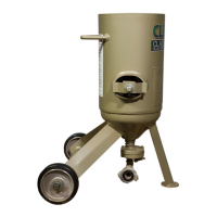
3.2.7 Make sure the choke valve is open; the valve is
open when the handle position is aligned with the piping,
as shown in Figure 10.
3.2.8 Close the abrasive metering valve. The FSV and
LPV (Lo-Pot valve) are closed when the handle is all the
way to either side of center; refer to Section 4.1. The
alternate MPV manual pinch-tube metering valve and
Quantum metering valves are closed when the metering
knob is turned fully clockwise. Manuals are provided with
alternate metering valves. NOTE: it is not necessary to
close the metering valve after the initial startup and
adjustment per Section 4.1.
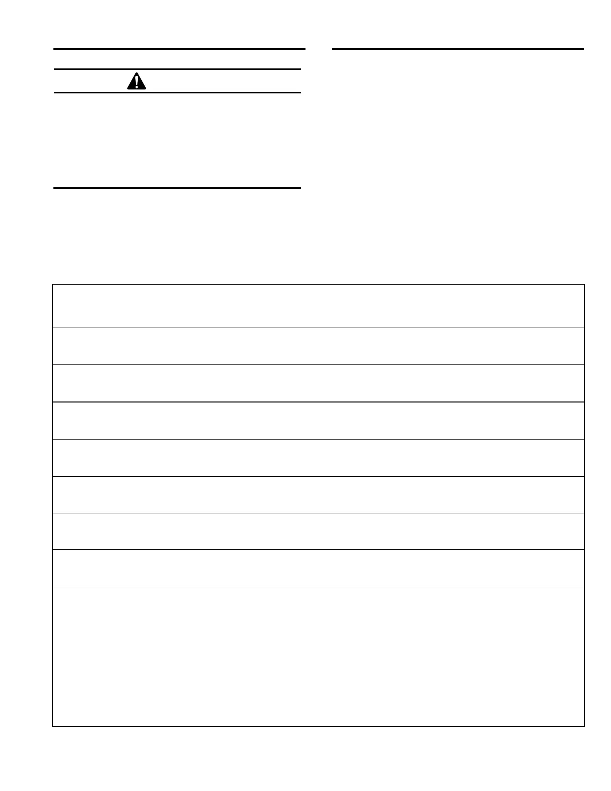
Compressed-Air and Abrasive Consumption
Consumption rates are based on abrasives that weigh 100 pounds per cubic foot
Nozzle Pressure at the Nozzle (psi) Air, Power,
Orifice and Abrasive
Size (in.) 50 60 70 80 90 100 125 140 Requirements
26 30 33 38 41 45 55 61 Air (cfm)
No. 3 150 171 196 216 238 264 319 353 Abrasive (lbs/hr)
3/16" 6 7 8 9 10 10 12 14 Compressor (hp)
47 54 61 68 74 81 98 108 Air (cfm)
No. 4 268 312 354 408 448 494 608 676 Abrasive (lbs/hr)
1/4" 11 12 14 16 17 18 22 24 Compressor (hp)
77 89 101 113 126 137 168 186 Air (cfm)
No. 5 468 534 604 672 740 812 982 1085 Abrasive (lbs/hr)
5/16" 18 20 23 26 28 31 37 42 Compressor (hp)
108 126 143 161 173 196 237 263 Air (cfm)
No. 6 668 764 864 960 1052 1152 1393 1538 Abrasive (lbs/hr)
3/8" 24 28 32 36 39 44 52 59 Compressor (hp)
147 170 194 217 240 254 314 347 Air (cfm)
No. 7 896 1032 1176 1312 1448 1584 1931 2138 Abrasive (lbs/hr)
7/16" 33 38 44 49 54 57 69 77 Compressor (hp)
195 224 252 280 309 338 409 452 Air (cfm)
No. 8 1160 1336 1512 1680 1856 2024 2459 2718 Abrasive (lbs/hr)
1/2" 44 50 56 63 69 75 90 101 Compressor (hp)
For nozzle sizes 3/8" to 1/2", blast machines should be equipped with 1-1/4" or larger piping and inlet valve to prevent
pressure loss.
Air requirements were measured by a flowmeter under actual blasting conditions and are, therefore, lower than figures for
air alone, with no abrasive.
Horsepower requirements are based on 4.5 cfm per horsepower.
Figures are for reference only and may vary for different working conditions. Several variables, including metering valve
adjustments, can affect abrasive flow.
Figures show approximate compressed air and abrasive consumption when nozzles are new. Consumption will increase as
the nozzle wears.
Figure 10