CLASSIC BLAST MACHINE with TLR-100/300 REMOTE CONTROLS Page 31
© 2018 CLEMCO INDUSTRIES CORP. www.clemcoindustries.com Manual No. 22501, Rev. I 02/18
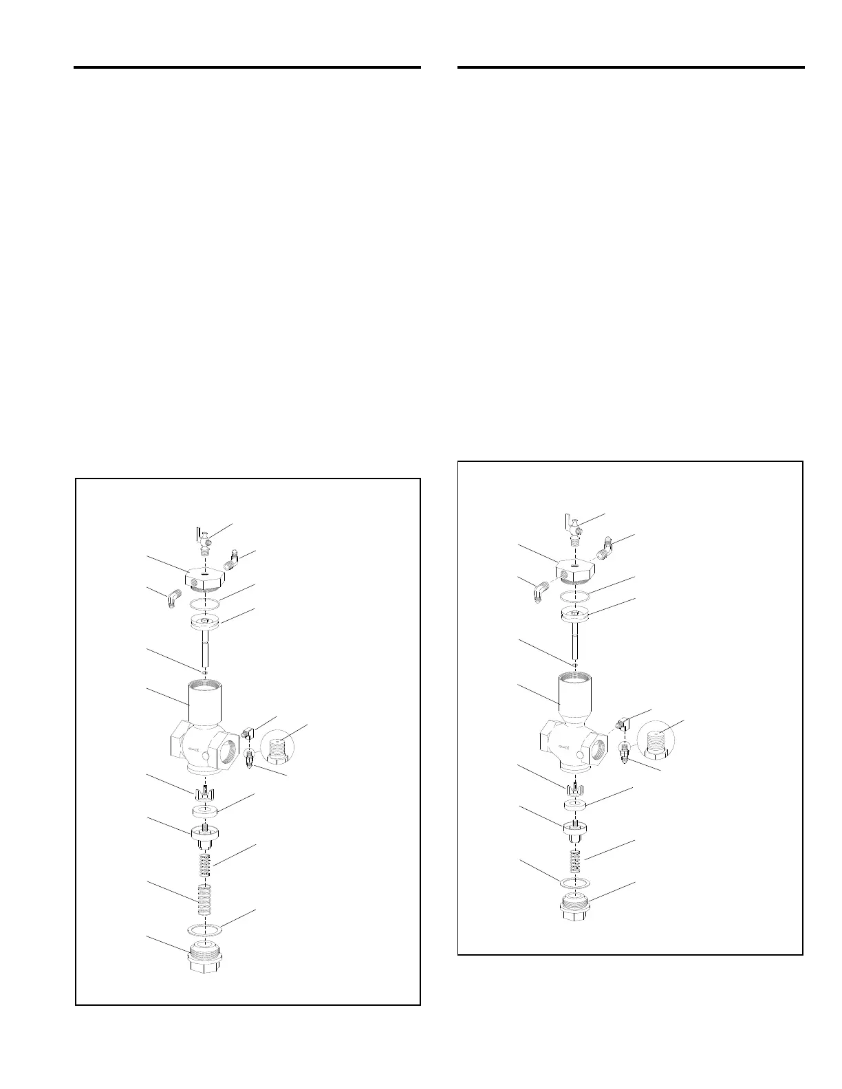
8.9 1-1/2" Inlet Valve, Figure 33
Item Description Stock No.
(-) 1-1/2" Inlet valve, complete ...................... 01995
1. Petcock 1/4" NPT ..................................... 01993
2. Elbow, 1/4" NPT adaptor .......................... 02513
3. Elbow, 1/8" NPT brass street ................... 03993
4. Adaptor 1/8" NPT with 1/16" orifice .......... 01945
5. Bottom cap ................................................ 02001
6.* Spring, inner, 5/8" x 1-11/16" long, (1) ..... 01982
7.* Gasket, bottom cap, (1) ............................ 02006
8.* Spring, outer, (1) ....................................... 02000
9. Valve body ................................................ 01996
10. Valve plug ................................................. 01999
11.* Washer, valve plug, (2) ............................. 01998
12.* Retainer, valve-plug washer, (1) .............. 02002
13.* O-ring, 7/16" OD, (1) ................................. 02008
14. Piston and rod assembly .......................... 02003
15.* O-ring 2-1/4" OD, (1) ................................ 02007
16. Cylinder cap .............................................. 01997
(-) Service kit, includes items marked *
quantities are shown in ( ) ......................... 01927
Figure 33
8.10 1" Inlet Valve, Figure 34
Item Description Stock No.
(-) 1" Inlet valve, complete ............................ 01980
1. Petcock 1/4" NPT .................................... 01993
2. Elbow, 1/8" NPT adaptor ......................... 02827
3. Elbow, 1/8" NPT brass street .................. 03993
4. Adaptor 1/8" NPT with 1/16" orifice ......... 01945
5. Bottom cap ............................................... 01985
6.* Spring, 5/8" x 1-11/16" long, (1) .............. 01982
7.* Seal, bottom cap, (1) ............................... 01989
8. Valve plug ................................................ 01984
9. Valve body ............................................... 01981
10.* Washer, valve plug, (2) ............................ 01969
11.* Retainer, valve-plug washer, (1) ............. 01986
12.* O-ring 3/16" ID x 1/16", (1) ...................... 01992
13. Piston and rod assembly ......................... 01987
14.* O-ring 1-3/4" OD, (1) ............................... 01990
15. Cylinder cap ............................................. 01983
(-) Service kit, includes items marked *
quantities are shown in ( ) ........................ 01929
Figure 34
s seen from
backside of fitting.
1
15*
13*
16
14
9
4
3
12*
11*
6*
7*
10
8*
5
2
2
1/16" Orifice
s seen from
backside of fitting.
2
1
2
3
4
5
6*
7*
8
9
10*
11*
12*
13
14*
15
1/16" Orifice