Disassembly
Removing the System Memory (RAM) -1 2 - 13
2.Disassembly
5. Pull the latches to release the second module if necessary.
6. Insert a new module holding it at about a 30° angle and fit the connectors firmly into the memory slot.
7. The module’s pin alignment will allow it to only fit one way. Make sure the module is seated as far into the socket
as it will go. DO NOT FORCE the module; it should fit without much pressure.
8. Press the module in and down towards the mainboard until the slot levers click into place to secure the module.
9. Replace the screws and shielding plate.
10. Replace the keyboard and make sure you reconnect the keyboard cable and keyboard LED cable.
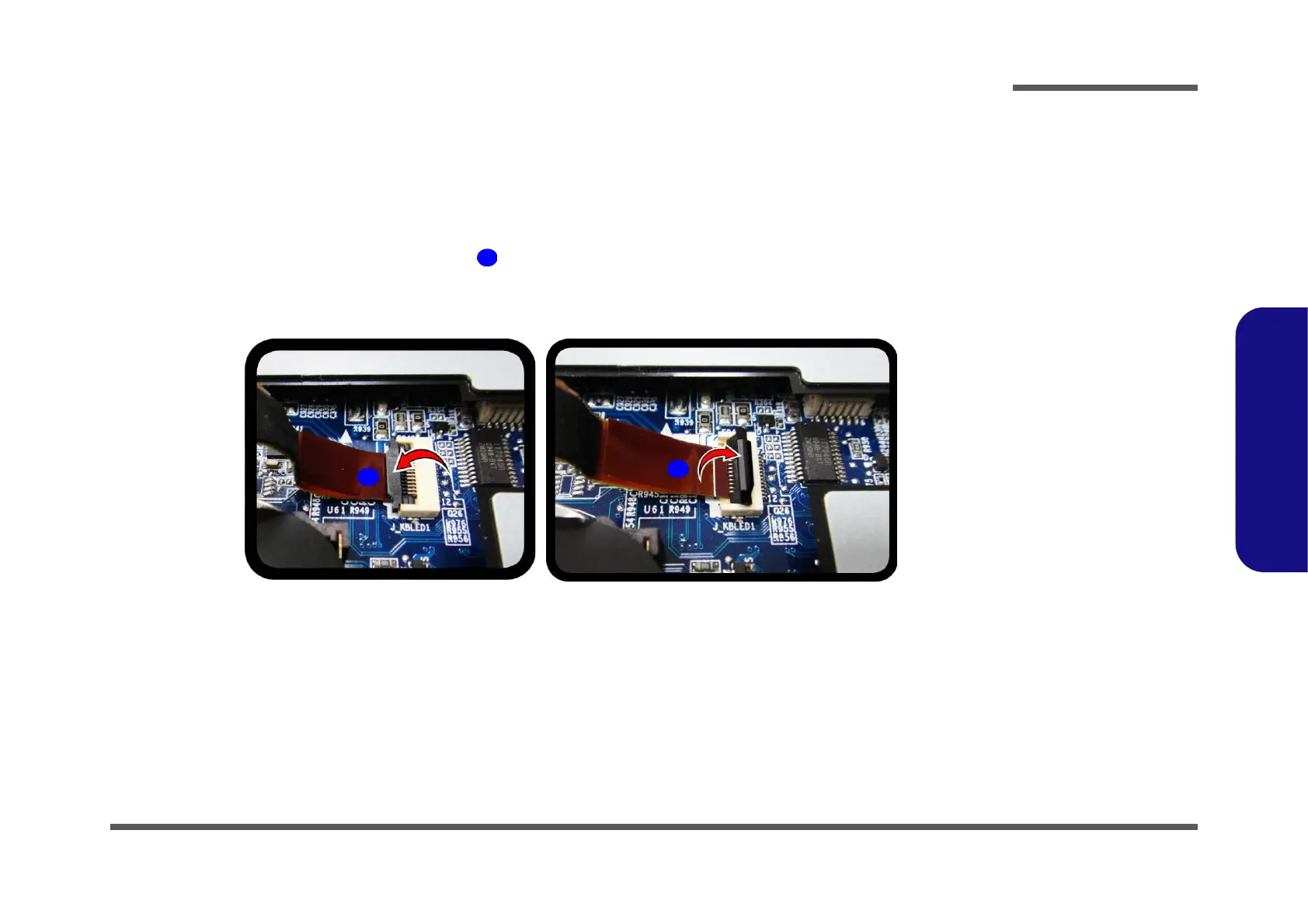
11. When reconnecting the keyboard LED cable , insert the cable so that the gold colored contact is facing upwards
to fit inside the connector. Make sure you tuck the cable into the recess in the shield plate to avoid trapping it
between the keyboard and the shielding plate.
12. Reconnect the LED module cable and reinstall the LEd cover module (see
Figure 7 on page 2 - 11).
13. Replace the screws on the bottom of the computer.
14. Restart the computer to allow the BIOS to register the new memory configuration as it starts up.
 Loading...