Disassembly
Removing the System Memory (RAM) from Under the Keyboard 2 - 13
2.Disassembly
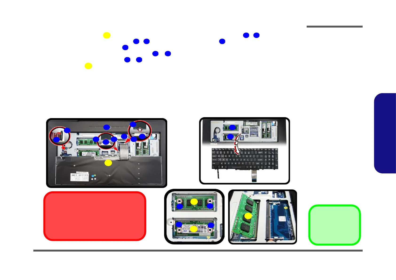
4. Carefully lift the keyboard up, being careful not to bend the keyboard ribbon cables - .
5. Disconnect the keyboard ribbon cables
- from the locking collar socket by using a small flat-head screw-
driver to pry the locking collar pins away from the base (Figure 8c).
6. Remove the keyboard and the memory sockets & will be visible (Figure 8d).
7. Gently pull the two release latches (
& ) on the sides of the memory socket(s) in the direction indicated below.
8. The RAM module will pop-up, and you can remove it (Figure 8e).
9. Pull the latches to release the second module if necessary.
10. Insert a new module holding it at about a 30° angle and fit the connectors firmly into the memory slot.
11. The module’s pin alignment will allow it to only fit one way. Make sure the module is seated as far into the slot as it
will go. DO NOT FORCE the module; it should fit without much pressure.
12. Press the module in and down towards the mainboard until the slot levers click into place to secure the module.
13. Replace the keyboard, bay cover and screws.
14. Restart the computer to allow the BIOS to register the new memory configuration as it starts up.
e.
11
d.
15
15
12
14
13
14
13
15
c.
8
9
10
7
10
10
6
10
5
9
9
Contact Warning
Be careful not to touch the metal pins on the mod-
ule’s connecting edge. Even the cleanest hands
have oils which can attract particles, and degrade
the module’s performance.
Figure 8
KB & RAM Module
Removal
c. Lift the keyboard up,
and disconnect the
keyboard ribbon cable
from the locking collar
socket.
d. Remove the keyboard
and the memory sock-
ets will be visible.
e. Pull the two release
latches on the sides of
the memory socket(s)
in the direction indicat-
ed.
5. Keyboard
15. RAM Modules
 Loading...