Disassembly
2 - 12 Removing the System Memory (RAM) from Under the Keyboard
2.Disassembly
Removing the System Memory (RAM) from Under the Keyboard
The computer has four memory sockets for 260 pin Small Outline Dual In-line (SO-DIMM) DDR 4 type memory modules.
The total memory size is automatically detected by the POST routine once you turn on your computer.
Two primary memory sockets are located under component bay cover (the bottom case cover), and two secondary
memory sockets are located under the keyboard. If you are installing only two RAM modules then they should be in-
stalled in the primary memory sockets under the component bay cover.
Memory Upgrade Process
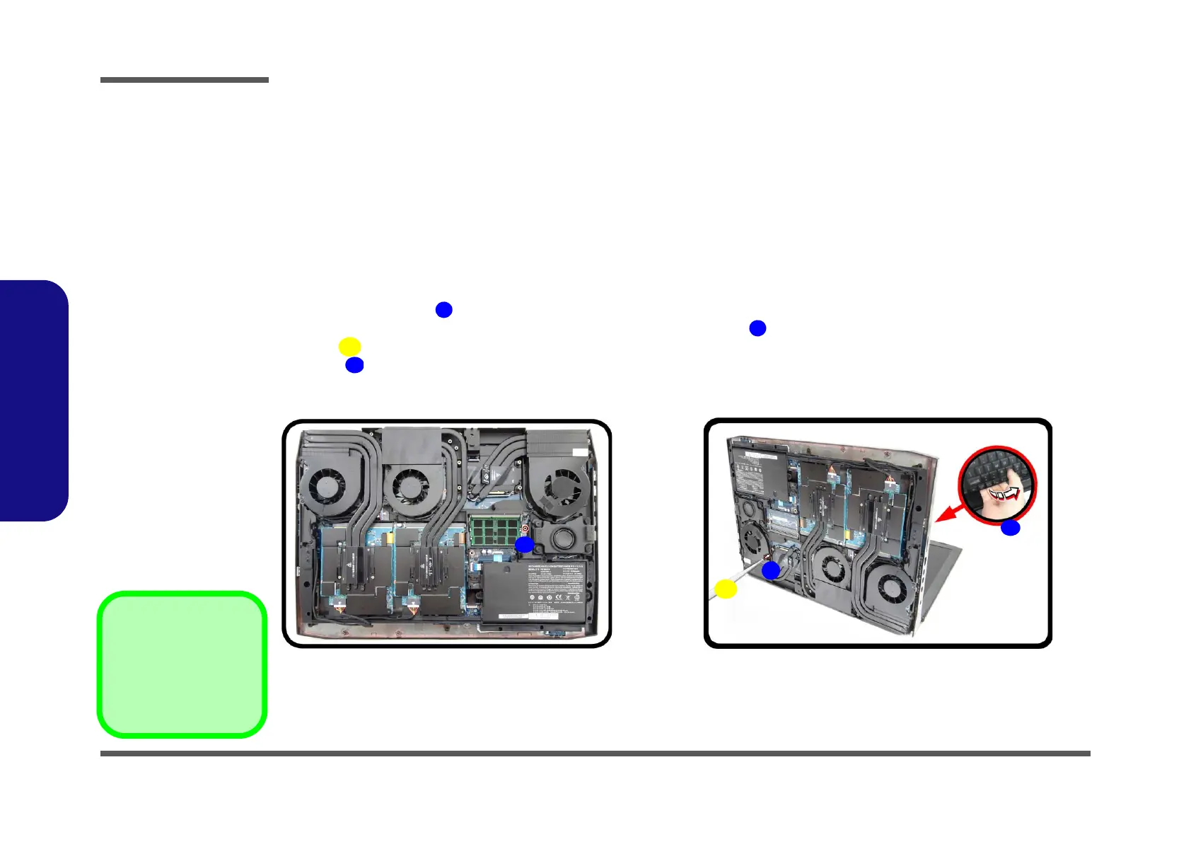
1. Turn off the computer, and turn it over, remove the battery (page 2 - 5).
2. Remove the screw
(Figure 7a).
3. Open it up with the LCD on a flat surface before pressing at point
to release the keyboard module (use an eject
stick with a diameter no bigger than 2.5mm) to do this while releasing the keyboard in the direction of the
arrow
as shown (Figure 7b).
Figure 7
Keyboard
Removal
a. Remove the screw.
b. Eject the keyboard
using a special eject
stick to push the
keyboard out while
releasing the key-
board as shown.
 Loading...