Do you have a question about the Clevo P170SM and is the answer not in the manual?
Identifies the product and document type.
Contains legal disclaimers, copyright, and revision information.
Lists registered trademarks of Intel and Microsoft.
Explains the manual's purpose, structure, and intended audience.
Provides critical safety precautions for using electrical equipment.
Offers suggestions for preventing damage to the notebook computer.
Advises on avoiding magnetic fields and proper peripheral device usage.
Outlines specific power requirements and precautions for the computer.
Details essential precautions and guidelines for handling and storing batteries.
Lists other manuals that may be useful for additional information.
Provides step-by-step instructions for starting the computer for the first time.
Introduces the manual's scope, covering servicing and upgrade information for the P170SM.
Details the technical specifications of the P170SM notebook computer.
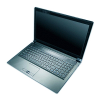
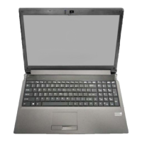
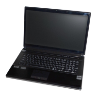
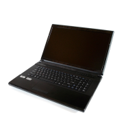
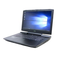
Identifies external components on the top view of the notebook with the LCD panel open.
Identifies external components on the front and right side views of the notebook.
Identifies external components on the left side and rear views of the notebook.
Identifies external components on the bottom view of the notebook, including bays and vents.
Warns about blocking vents and fans to prevent overheating.
Identifies key components on the top side of the mainboard.
Identifies key components on the bottom side of the mainboard.
Identifies various connectors on the top side of the mainboard.
Identifies various connectors on the bottom side of the mainboard.
Introduces the disassembly chapter, explaining procedures and providing guidance on information boxes.
Lists recommended tools and describes the four types of electrical connections within the computer.
Details precautions for personal safety, computer integrity, and cleaning methods.
Emphasizes turning off power and disconnecting components before upgrade procedures.
Provides a table listing disassembly procedures and corresponding page numbers.
Step-by-step instructions for safely removing the battery from the notebook.
Instructions for removing the primary hard disk drive to accommodate a new one.
Important warnings regarding data backup and installation of a new hard disk.
Continues the procedure for removing the hard disk assembly and insulation plate.
Provides information on foam rubber inserts for 7mm(H) hard disk drives.
Step-by-step instructions for removing the Solid State Drive module.
Instructions for removing the optical drive from its bay.
Continues the procedure for removing and attaching the optical device bezel.
Instructions for removing the secondary hard disk drive if installed.
Continues the procedure for removing the secondary HDD assembly and its insulation plate.
Instructions for removing and upgrading primary system memory modules.
Details the steps for upgrading the primary RAM modules.
Continues the procedure for lifting the component bay cover and removing RAM modules.
Warns about touching RAM module pins to prevent static discharge and performance degradation.
Instructions for removing secondary system memory modules located under the keyboard.
Details the steps for upgrading secondary RAM modules, including keyboard removal.
Continues the procedure for disconnecting cables and removing RAM modules.
Warns about touching RAM module pins to prevent static discharge and performance degradation.
Step-by-step instructions for removing the Wireless LAN module.
Instructions for removing the MSATA module.
Details the steps for removing the processor, including heat sink removal.
Warns about potential damage to CPU pins and the need to remove the WLAN module first.
Continues the processor removal by turning the release latch and lifting the CPU.
Advises allowing hot components like the heat sink and CPU area to cool before removal.
Step-by-step instructions for installing a new processor, including heat sink and fan replacement.
Details the steps for removing the video card, including heat sink removal.
Warns about high temperatures in the heat sink and video card area.
Provides specific instructions for removing and tightening heat sink screws.
Specific steps for removing the video card assembly and shielding plate for the N14E-GTX model.
Instructions for installing a new video card, ensuring proper seating and connection.
Warns about high temperatures in the heat sink and video card area during installation.
Step-by-step instructions for removing the CCD module from the LCD panel assembly.
Instructions for removing the top cover, including disconnecting cables and removing fan units.
Continues the top cover removal by removing screws and separating the top and bottom cases.
Explains that the appendix details the P170SM notebook's construction with component part numbers.
Provides a table indicating where to find illustrations for specific part lists.
Illustration and list of parts for the top assembly with a fingerprint reader.
Illustration and list of parts for the top assembly without a fingerprint reader.
Illustration and list of parts for the bottom assembly, N14E-GS model.
Illustration and list of parts for the bottom assembly, N14E-GTX model.
Illustration and list of parts for the LCD assembly.
Illustration and list of parts for the COMBO drive assembly.
Illustration and list of parts for the DVD-Dual Drive assembly.
Lists all available schematic diagrams and their corresponding page numbers.
Provides a high-level overview of the P150SMShark Bay system architecture.
Detailed schematic diagram of the processor interface, including DMI, FDI, and PEG signals.
Schematic diagram for the processor, covering miscellaneous, JTAG, and clock signals.
Schematic diagram of the processor, detailing DDR3 memory interfaces.
Schematic diagram for the processor, focusing on display interfaces like eDP, DDI, and HDMI.
Schematic diagram for the processor, detailing power management and SVID signals.
Schematic diagram for the processor, primarily showing ground (GND) connections.
Schematic diagram for the processor, covering reserved signals, CFG straps, and PCI Express bifurcation.
Schematic diagram for the Channel A SO-DIMM 0 memory slot, detailing DDR3 interfaces.
Schematic diagram for the Channel A SO-DIMM 1 memory slot, detailing DDR3 interfaces.
Schematic diagram for the Channel B SO-DIMM 1 memory slot, detailing DDR3 interfaces.
Schematic diagram for the Channel B SO-DIMM 0 memory slot, detailing DDR3 interfaces.
Schematic diagram for the MXM PCI-E interface, detailing connections for graphics modules.
Schematic diagram for the CRT panel interface, including LVDS and eDP connections.
Schematic diagram for the PS8625 component, likely a power or display related IC.
Schematic diagram for the 1394a (FireWire) controller, XIO2221.
Schematic diagram showing the Display Port interface connections.
Schematic diagram illustrating the HDMI interface connections.
Schematic diagram for the PCH, covering RTC, HDA, SATA, and JTAG interfaces.
Schematic diagram for the PCH, detailing LPC, SMBUS SPI, and C-LI interfaces.
Schematic diagram for the PCH, covering DMI, FDI, and PWRGD signals.
Schematic diagram for the PCH, detailing CRT, Display, and PCI interfaces.
Schematic diagram for the PCH, covering PCIe and USB interfaces.
Schematic diagram for the PCH, detailing GPIO and CPU interfaces.
Schematic diagram for the PCH, focusing on power delivery and regulation circuits.
Schematic diagram for the PCH, detailing additional power circuits.
Schematic diagram for the PCH, illustrating clock signals and ground connections.
Schematic diagram for USB 3.0 ports and USB charging circuitry.
Schematic diagram covering USB 2.0 ports, CCD module, Mini PCIE slot, and LID switch.
Schematic diagram for LED indicators, hotkey functions, LID switch, and fan control.
Schematic diagram for the RJ45 Ethernet port, including magnetics.
Schematic diagram for the Realtek ALC892 audio codec and associated circuitry.
Schematic diagram for the APA2607 and TPA2008D2 audio amplifier ICs.
Schematic diagram for the ITE IT8587B Keyboard Controller.
Schematic diagram related to the keyboard backlight control.
Schematic diagram covering mSATA, fan control, touchpad, fingerprint, and multi-connector interfaces.
Schematic diagram for the Realtek RTL8411 card reader.
Schematic diagram for the USB 3.0 port interface.
Schematic diagram for DDR memory voltage regulation and PCH 1.5V supply.
Schematic diagram for the VDD3 and VDD5 power rails.
Schematic diagram for the 5VS, 3.3VS, and 1.5VS power rails.
Schematic diagram for the 1.05VS power rail and 1.05V LAN power.
Schematic diagram for the V-Core 1 power delivery system.
Schematic diagram for the AC adapter input and battery charging circuitry.
Schematic diagram for the Trusted Platform Module (TPM) controller.
Schematic diagram for the audio circuitry, including jacks and codec connections.
Schematic diagram for the Optical Disk Drive board.
Schematic diagram for the click board, possibly related to input devices or sensors.
Schematic diagram for the P170 click board, likely related to input devices or sensors.
Schematic diagram for the P170 fingerprint reader board.
Schematic diagram for the P150 HDD board.
Schematic diagram for the left LED board on the P150 model.
Schematic diagram for the right LED board on the P150 model.
Schematic diagram for the mSATA interface board.
Illustrates the sequence of power signals during system startup.
Lists the essential steps required before updating the FLASH ROM BIOS.
Provides important notes regarding correct BIOS version selection and compatibility.
Details the process of using flash tools to update the BIOS from a bootable drive.
Instructions for restarting the computer, entering BIOS, and loading default settings.
| RAM | Up to 32GB DDR3 |
|---|---|
| Chipset | Intel HM87 |
| Processor | Intel Core i7-4700MQ |
| Graphics | NVIDIA GeForce GTX 780M |
| Display | 17.3" FHD (1920 x 1080) |
| Storage | Up to 3x HDD/SSD (2.5" and mSATA) |
| Operating System | Windows 8.1 |
| Ports | USB 3.0, HDMI, Mini DisplayPort, Ethernet, Audio Jack |
| Wireless | Wi-Fi 802.11ac, Bluetooth 4.0 |
| Battery | 8-cell |