Do you have a question about the Clevo P150SM-A and is the answer not in the manual?
If the computer falls, the case and the components could be damaged.
Keep the computer and power supply away from any kind of heating element.
Shut the computer down properly and don't forget to save your work.
Warning about removing covers and screws for device upgrades.
Warning about turning off power and disconnecting before upgrade procedures.
Keep computer away from transformers, motors, and strong magnetic fields.
Use approved peripherals and unplug power cord before attaching.
Computer requires specific power adapter and steady, uninterrupted power supply.
Only use batteries designed for this computer. Wrong battery may explode, leak, or damage.
Guidelines for backup batteries, including removal for storage and charging.
Information on recycling rechargeable batteries according to local laws.
How to check current battery level and charge status in the taskbar.
Lists other manuals that may be needed for additional information.
Step-by-step guide for initial computer setup, including unpacking and connecting.
Specifications are current at press time; items may change due to manufacturer schedules.
The CPU is not user-serviceable; accessing it may violate warranty.
Lists available Intel Core i7/i5/i3 processor models and their specs.
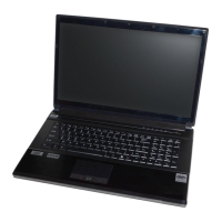
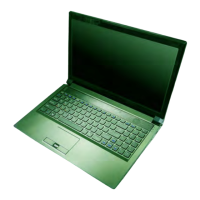
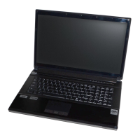
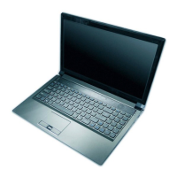
Details about the notebook's 15.6-inch FHD LCD screen.
Information on memory sockets and maximum supported DDR3L 1600MHz RAM.
Specifies the Intel HM87 Express Chipset used in the system.
Details on security features like Kensington lock slot, BIOS password, fingerprint reader.
Options for storage devices including optical drives, HDDs, and mSATA SSDs.
Information about the AMI BIOS (48Mb SPI Flash-ROM).
Details on integrated Intel GPU and discrete NVIDIA GPUs.
Details Intel HD Graphics 4600 with dynamic frequency and DirectX 11 support.
Lists NVIDIA GeForce GTX 800M series GPUs with GDDR5 RAM and DirectX 11.1.
Description of the built-in touchpad with integrated scrolling key functionality.
Information on the illuminated full-size WinKey keyboard with numeric keypad.
Features of the High Definition Audio interface including S/PDIF, speakers, and microphone.
Details on slots for WLAN modules and mSATA SSDs.
Description of the embedded multi-in-1 push-push card reader.
List of external ports including USB 3.0, USB 2.0, eSATA, HDMI, DisplayPort.
Details on built-in Gigabit Ethernet LAN and FHD PC Camera.
Options for wireless communication modules like Intel Centrino and Wireless-AC.
Specifications for operating temperature and relative humidity.
Details on the 8-cell battery pack and AC/DC adapter specifications.
Physical dimensions and weight of the notebook computer.
Diagram showing the top view of the laptop with labeled components.
Identifies external components on the top view: camera, microphone, speakers, buttons, LEDs.
Diagram showing the front view with labeled LED power indicators.
Diagram showing the right side view with labeled ports and slots.
Diagram showing the left side view with labeled ports and slots.
Diagram showing the rear view with labeled ports and vents.
Diagram showing the bottom view with labeled vents, covers, woofer, HDD bay, and battery.
Warning to prevent overheating by ensuring vent/fan intakes are not blocked.
Lists recommended tools for notebook PC maintenance and disassembly.
Describes four types of internal computer connections and how to release them.
Essential precautions for safe disassembly and component handling to prevent injury or damage.
Guidelines for safely cleaning the computer's exterior components.
Crucial safety warning before disassembly: turn off power, disconnect all, remove battery.
Step-by-step instructions for safely removing the laptop's battery.
Procedure for removing the primary hard disk drive for upgrade or replacement.
Important warning regarding data backup and OS/driver readiness for HDD replacement.
Continues the hard disk assembly removal process, detailing screws and insulation plates.
Instructions for installing a new hard disk assembly into the drive bay.
Procedure for removing the Solid State Drive (SSD) from its location.
Step-by-step guide to remove the optical CD/DVD drive from the computer.
Continues the optical device removal, focusing on bezel detachment and reattachment.
Procedure to remove a secondary hard disk located in the optical drive bay.
Instructions for removing primary RAM modules located under the bottom case cover.
Continues RAM removal by accessing modules under the component bay cover and using release latches.
Warning about handling RAM modules to prevent static discharge and contamination.
Procedure to remove secondary RAM modules located beneath the keyboard assembly.
Continues RAM removal under keyboard: disconnect ribbon cable, release latches, remove module.
Step-by-step guide to remove the Wireless LAN module.
Procedure for removing the MSATA module from the computer.