This appendix has circuit diagrams of the W670RCQ notebook’s PCB’s. The following table indicates where to find the
appropriate schematic diagram.
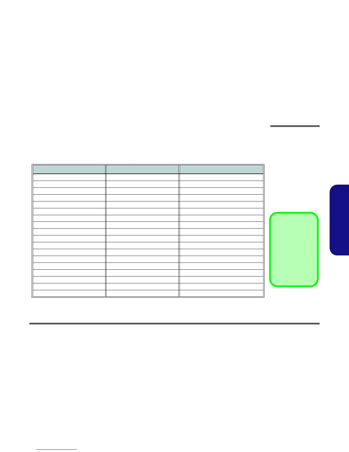
Diagram - Page Diagram - Page Diagram - Page
System Block Diagram - Page B - 2 CRT - Page B - 20 5V, 5VS, 3.3V, 3.3VS, 3.3VA - Page B - 38
Processor 1/7 - Page B - 3 PCH 1/9 - Page B - 21 1.0V, VCCIO - Page B - 39
Processor 2/7 - Page B - 4 PCH 2/9 - Page B - 22 VDD3, VDD5 - Page B - 40
Processor 3/7 - Page B - 5 PCH 3/9 - Page B - 23 DDR3L 1.35V / 0.75VS - Page B - 41
Processor 4/7 - Page B - 6 PCH 4/9 - Page B - 24 POWER VCORE - Page B - 42
Processor 5/7 - Page B - 7 PCH 5/9 - Page B - 25 VCC_Core & VCCSA - Page B - 43
Processor 6/7 - Page B - 8 PCH 6/9 - Page B - 26 1.0DX_VCCSTG / VCCSFR_OC - Page B - 44
Processor 7/7 - Page B - 9 PCH 7/9 - Page B - 27 VCCGT - Page B - 45
DDR3 CHA SO-DIMM_0 - Page B - 10 PCH 8/9 - Page B - 28 VCCGT Output Stage - Page B - 46
DDR3 CHB SO-DIMM_0 - Page B - 11 PCH 9/9 - Page B - 29 AC_In, Charger - Page B - 47
PS8625 - Page B - 12 M.2 3G + M.2 SATA - Page B - 30 N16P/S, NVVDD, PEX, FBVDDQ - Page B - 48
PANEL, INVERTER - Page B - 13 M.2 WLAN+BT, PCIE4X SSD - Page B - 31 USB Charge, CCD, TPM, Power Conn - Page B - 49
VGA PCI-E Interface - Page B - 14 USB3.0, LED - Page B - 32 Audio Board - Page B - 50
VGA Frame Buffer Interface - Page B - 15 Card Reader (RTL8411B) - Page B - 33 Power Switch Board - Page B - 51
VGA Frame Buffer A - Page B - 16 HDD, TP, Audio, USB - Page B - 34 ODD to HDD Board - Page B - 52
VGA Frame Buffer C - Page B - 17 HDMI - Page B - 35
VGA I/O - Page B - 18 AUDIO CODEC ALC269 VC2 - Page B - 36
VGA NVVDD Decoupling - Page B - 19 KBC-ITE IT8587 - Page B - 37
 Loading...