WWW.CLF-LIGHTING.COM
6
Power cables
Power input and throughput cables must be rated 16A minimum, have three conductors 1.5 mm² (16 AWG) minimum conductor size and
an outer cable diameter of 5 - 15 mm. Cables must be hard usage type (SJT or equivalent) and heat- resistant to 90°C minimum. In the
EU the cable must be HAR approved or equivalent.
If you install a power plug on the power cable, install a grounding-type (earthed) plug that is rated 16A minimum. Follow the plug
manufacturer’s instructions. Table 1 shows standard wire color-coding schemes and some possible pin identication schemes; if pins are
not clearly identied.
Data link
A DMX 512 data link is required in order to control a xture via DMX. The xture has 5-pin XLR connectors for DMX data input and output.
The pin-out on all connectors is pin 1 = shield, pin 2 = cold (-), and pin 3 = hot (+) Pins 4 and 5 in the 5-pin XLR connectors are not used.
Tips for reliable data transmission
To connect the xture to data:
1. Connect the DMX data output from the controller to the 5-pin XLR connector of the nearest xture.
2. Connect the DMX output of the xture closest to the controller to the DMX input of the next xture and continue connecting xtures
output to input.
Relaying power to other devices
Warning! Do not connect more than ve xtures in total to AC mains power in one interconnected chain. Power can be relayed to another
device via the PowerCON TRUE 1 ® throughout socket.
If you daisy chain the xtures in a chain so that they all draw AC mains power via the rst xture, certain points must be respected:
A heavy duty, three-conductor, 16 AWG or 1.5 mm2 cable with SJT or equivalent cable jacket must be used to connect the rst xture to
AC mains power.
• PowerCON TRUE 1 ® connectors must be used to draw AC mains power from the xtures power throughout sockets and yellow
PowerCON TRUE 1 ® connectors must be used to supply power at the xture’s power input sockets.
• No matter what the AC mains power voltage is, do not connect more than the xture in total ( including the rst xture) to AC mains
power in one interconnected daisy chain using power input and through out connectors.
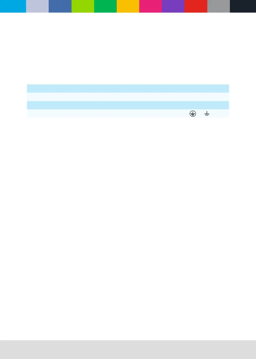
Wire Color (EU models) Wire Color (US models) Conductor Symbol
Brown Black Live L
Blue White Neutral N
Yellow/Green Green Ground (earth) or
Table 1 : Wire color-coding and power connections