climatemaster.com
3
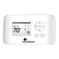
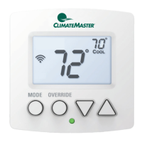
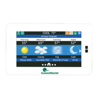
iGate
®
ConnectProgrammableThermostat
Revised:December20,2021
THE SMART SOLUTION FOR ENERGY EFFICIENCY
TECHNICAL SUPPORT
Ourtechnicalsupportteamisavailabletoansweryour
questionsat1.405.745.6000.
BEFORE YOU BEGIN
Thisproductisintendedtobeinstalledbytrainedservice
professionals.
Thismanualexplainstheproceduresforinstallingthe
ClimateMasteriGate
®
Connectthermostat.Pleasereadit
carefullybeforebeginningtheinstallation.
ForinformationonhowtooperatetheClimateMaster
iGateConnectthermostat,pleaseseetheiGateConnect
ThermostatUserManual.
TheiGateConnectthermostatisdesignedtobemounted
onthehomeowner’swallinaconvenientlocation.
SPECIFICATIONS
Power 24 VAC +/- 10% @ 3 VA
Dimensions
3.52 in. (90 mm) W x 2.52 in. (64 mm) H
x 0.83 in. (21 mm) D
Network Requirements
Wi-Fi connectivity supports Wi-Fi: 802.11
a/b/g/n standards on 2.4 GHz networks
Environmental Operating Range
32° to 104° (0° to 40°C), 10 to 95%
relative humidity, non-condensing
Mounting
Standard 4x2-in. electrical box using the
6-32 x 1/2” mounting screws provided
Listed by FCC Part 15, Subpart J compliant
WIRING REQUIREMENTS
Thefollowingtableshowsthemaximumwirelengths
allowed:
Thermostat to HVAC Equipment
18 AWG 20 AWG 22 AWG
1250 ft/380 m 800 ft/240 m 500 ft/150 m
INSTALLATION CONSIDERATIONS
Thethermostatrequiresnobatteries.Thethermostatis
notapowerstealingdeviceandMUSThavebothRandC
terminalsconnected.SeeDiagram1.
INSTALLATION
Thermostat Location
Thermostatshouldbemounted:
• Approximately5ft.(1.5m)aboveoor.
• Closetoorinafrequentlyusedroom,preferablyon
aninsidepartitioningwall.
• Onasectionofwallwithoutpipesorductwork.
Thermostat should NOT be mounted:
• Closetoawindow,onanoutsidewall,ornexttoa
doorleadingtotheoutside.
• Exposedtodirectlightandheatfromalamp,sun,
replace,orothertemperature-radiatingobjectwhich
maycauseafalsereading.
• Closetoorindirectairowfromsupplyregisters
• Inareaswithpooraircirculation,suchasbehinda
doororinanalcove.
Thermostat Installation
1. TurnSystemPowerOff.
a. Gototherelevantcircuitbreakerpaneland
switchtheequipmentbreakersoff.
b. Toconrmpowerisoff,checkvoltagewith
voltmetertoensurethatthepowerhasbeen
successfullyshutoffbeforeproceedingto
nextstep.
Disconnect electric power to the HVAC system before
installing this product. Failure to do so could result in
electric shock and/or equipment damage. All wiring must
conform to you local electrical code.
⚠
CAUTION
If you are replacing a current communicating
thermostat continue with the next step, if you are
installing a new system skip to step 5.
2. Removethefaceplateofthecurrentthermostat.Most
faceplatessnapofforfeaturesmallscrewsthatwill
needtoberemoved.
TIP: Before disconnecting any wires, take a photo
of the current wire conguration with your mobile
device.
MERCURY NOTICE: This product does not contain
mercury. If you are replacing a product that
does contain mercury, contact your local waste–
management authority for disposal instructions.
Do not discard the old product in the regular trash.
3. LabelandDisconnectWires.
Onebyone,applyalabeldesignatedtoeachwire
connectedtothebackplateofthecurrentthermostat
thendisconnectthewirefromthecurrentthermostat
backplate.
 Loading...