iGate
®
ConnectProgrammableThermostat
Revised:December20,2021
ClimateMaster Water-Source Heat Pumps
4
CLIMATEMASTER WATER-SOURCE HEAT PUMPS
TIP: Wrap the wires around a pen or
pencil to keep them from falling inside
the wall.
4. Removethecurrentbackplate.
5. Mountthenewbase.
a. Gentlyseparatethedisplayfromthebaseofthe
newthermostatbypullingthermostatstraight
awayfromthebase.
b. Positionthebaseagainstthewallanddetermine
ifwallanchorsfromcurrentthermostatalignwith
screwlocationsofnewbase.
c. Ifbasedoesnotalignwithexistinganchorholes,
marknewscrewlocationswithapencil.
• Drywall:Drill3/16”holefortheanchor.
• Plaster:Drill7/32”holefortheanchor.
d. Pullwiresthroughopeninginbaseandsecureto
thewallusingprovidedscrews.
TIP: Use a level to ensure thermostat
is properly aligned.
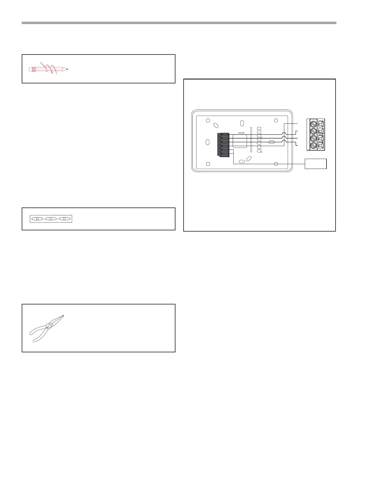
6. Connectwires.
a. Matchyourwirecongurationtotheterminalson
thebase.ReferenceDiagram1.
b. Connecteachwireindividuallybypushingdown
onthequickconnecttab,insertingthewireinto
theconnectoropening,andthenreleasingthetab.
c. Ifremoteindoorand/oroutdoorsensorsareused,
theymaybeconnectedatthistime.
TIP: Use pliers to straighten wire before
inserting into new base. Be sure to cut any
excess wire so that the insulation extends
to the terminal block. When the wire is
installed properly to the terminal block,
there should be no copper exposed.
22 AWG shielded wire is required when installing a
remote sensor further than 100 ft (30.5 meters).
7. Attachthethermostatface.
a. Alignthethermostatfaceusinghingeguideontop.
b. Rotatethethermostatdownuntiltabalignswith
holeinbase.
c. Installsecurityscrewifnecessary.
8. Returnpowertosystem.
Wiring Diagram
Allexcesswireshouldbepushedbackintothewallasfar
aspossible.
A+
B-
C
R
S1
S2
Thermostat
Remote
Sensor
R
B-
C
A+
Unit Control
Diagram 1: Thermostat Connections
Thermostat Connections
A+ Communications (Positive)
B– Communications (Negative)
C 24V Common for Control Circuit
R 24V Supply for Control Circuit
S
1
Remote Sensor
S
2
Remote Sensor
SYSTEM CONFIGURATION
From the thermostat display:
1. ToconguretheSystemSettingsusingthemyUplink
PROmobileapp,setthethermostatSystemMode
to“OFF”.
2. Swipeleftorrightonthethermostatscreenuntilyou
reachtheFanscreen.
3. PresstheFanbuttonfor5secondstoenablethe
“SystemSettings”screen.
4. Scrolldowntoselectthe“APAccess”option.
5. Select“YES”toenable.
From the myUplink PRO app:
6. Withyourmobiledevicewithin15ftofthe
thermostat,openandlogintoyourmyUplink
PROapp.
7. FromtheSystemsscreen,selectthegreen“add”
buttonatthetopright.
8. Selectthe“ConnectLocally”.Theappwillndany
devicesinAccessPointmode.
 Loading...