CLIMATEMASTER WATER-SOURCE HEAT PUMPS
Tranquility
®
20 (TS) Series
Rev.: June 5, 2020
ClimateMaster Water-Source Heat Pumps
12
Vertical Installation, Cont’d.
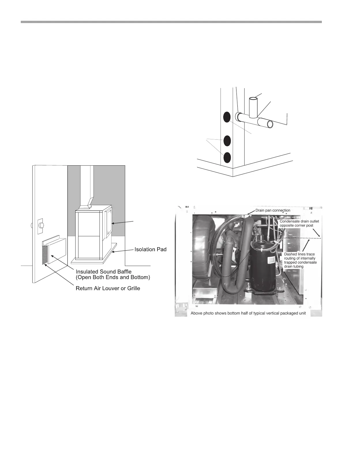
Sound Attenuation for Vertical Units - Sound
attenuation is achieved by enclosing the unit within a
small mechanical room or a closet. Additional measures
for sound control include the following:
1. Mount the unit so that the return air inlet is 90° to the
return air grille. Refer to Figure 9. Install a sound bafe
as illustrated to reduce line-of sight sound transmitted
through return air grilles.
2. Mount the unit on a rubber or neoprene isolation pad
to minimize vibration transmission to the building
structure.
Return
Air Inlet
Figure 9: Vertical Sound Attenuation
Condensate Piping for Vertical Units - A condensate
line must be installed and pitched away from the unit to
allow for proper drainage. This connection must meet
all local plumbing/building codes. Vertical units utilize a
condensate hose inside the cabinet as a trapping loop;
therefore an external trap is not necessary. Figure 10a
shows typical condensate connections. Figure 10b
illustrates the internal trap for a typical vertical heat pump.
Each unit must be installed with its own individual vent
(where necessary) and a means to ush or blow out the
condensate drain line. Do not install units with a common
trap and/or vent.
Vent
*3/4" FPT
3/4" PVC
Alternate
Condensate
Location
Water
Connections
* Some units include a painted drain connection. Using a
threaded pipe or similar device to clear any excess paint
accumulated inside this fitting may ease final drain line installation.
1/8" per foot
slope to drain
Figure 10a: Vertical Condensate Drain
Figure 10b: Vertical Internal Condensate Trap
Notice! Units with clear plastic drain lines should have
regular maintenance (as required) to avoid buildup of
debris, especially in new construction.
 Loading...