EasyManua.ls Logo

ClimateMaster Tranquility 20 TSH 006 Series User Manual

ClimateMaster Tranquility 20 TSH 006 Series
64 pages
To Next Page IconTo Next Page
Page #1 background imageLoading...
Page #1 background image
Tranquility
®
20
(TS) Series
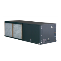
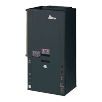
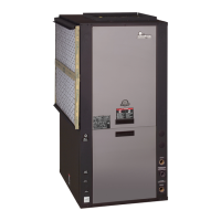
Models TSD/H/V 006 - 070
60Hz - HFC-410A
INSTALLATION, OPERATION
& MAINTENANCE
97B0075N06
Revised: 17 June, 2015
Model Nomenclature - General Overview 3
General Information 4
Unit Physical Data 6
Horizontal Installation 7
Field Conversion of Air Discharge 9
Horizontal Installation 10
Vertical Installation 11
Piping Installation 13
Water-Loop Heat Pump Applications 14
Ground-Loop Heat Pump Applications 15
Ground-Water Heat Pump Applications 17
Water Quality Standards 19
Electrical - Line Voltage 20
Electrical - Power Wiring 26
Electrical - Power & Low Voltage Wiring 27
Electrical - Low Voltage Wiring 28
Electrical - Thermostat Wiring 29
TS Blower Performance Data - (ECM Motor) -
Standard Unit - No Reheat 30
TS Blower Performance Data - Standard Unit -
No Reheat (PSC Motor) 31
TS Blower Performance Data - Units with
ClimaDry
®
(PSC Motor) 32
ECM Blower Control 33
Typical Wiring Diagram - Units with CXM Board
and ECM Fan Motor (Single Phase) 35
Typical Wiring Diagram - Units with CXM Board
and PSC Fan Motor (Single Phase) 36
CXM Controls 39
DXM Controls 40
Safety Features - CXM and DXM Controls 42
ClimaDry
®
Modulating Reheat Option 44
Piping System Cleaning and Flushing 47
Unit and System Checkout 49
Unit Start-Up Procedure 50
Unit Operating Conditions 52
ClimaDry
®
II Option Corrections
(When Operating in Non-ClimaDry
®
Mode) 52
Preventive Maintenance 57
Functional Troubleshooting 58
Performance Troubleshooting 59
Start-Up Log Sheet 60
Functional Troubleshooting 61
Warranty (U.S. & Canada) 62
Warranty (International) 63
Revision History 64

Questions and Answers:

ClimateMaster Tranquility 20 TSH 006 Series Specifications

General IconGeneral
BrandClimateMaster
ModelTranquility 20 TSH 006 Series
CategoryHeat Pump
LanguageEnglish

Summary

Safety

Pre-Installation

Unit Physical Data

Horizontal Installation

Mounting Horizontal Units

Instructions for suspending horizontal units using hanger kits and vibration isolators.

Condensate Piping - Horizontal Units

Guidelines for installing and pitching condensate drain lines for horizontal units, including trap requirements.

Duct System Installation

Critical considerations for proper duct sizing and design to ensure unit performance and quiet operation.

Vertical Installation

Condensate Piping for Vertical Units

Instructions for installing vertical unit condensate lines, noting internal trap usage.

Piping Installation

Ground-Loop Heat Pump Applications

Piping Installation

Recommendations for closed loop ground source piping materials and fittings to prevent corrosion and leaks.

Electrical - Line Voltage

Electrical - Power Wiring

Blower Speed Selection – Units with PSC Motor

Instructions for changing PSC blower fan speed by repositioning motor wires for optimal airflow.

Electrical - Power & Low Voltage Wiring

Thermostat Connections

Wiring instructions for thermostats to CXM/DXM boards or ECM interface boards for PSC and ECM motors.

Low Water Temperature Cutout Selection

Field selection of low water temperature limits via JW3 jumper on CXM/DXM controls for antifreeze systems.

Electrical - Low Voltage Wiring

Water Solenoid Valves

Use of external solenoid valves for shutting off flow, reducing water hammer, and thermostat compatibility.

Electrical - Thermostat Wiring

Thermostat Installation

Guidelines for locating and mounting thermostats, ensuring proper temperature measurement and wiring.

TS Blower Performance Data - (ECM Motor) - Standard Unit - No Reheat

TS Blower Performance Data - Standard Unit - No Reheat (PSC Motor)

TS Blower Performance Data - Units with ClimaDry® (PSC Motor)

ECM Blower Control

Cooling settings

Defines cooling airflow settings for ECM units based on DIP switch selection, ensuring no air coil freeze-up.

Heating Settings

Specifies heating airflow settings for ECM units based on DIP switch selection, correlating to CFM output.

Typical Wiring Diagram - Units with CXM Board and ECM Fan Motor (Single Phase)

Typical Wiring Diagram - Units with CXM Board and PSC Fan Motor (Single Phase)

Typical Wiring Diagram - Units with DXM Board and PSC Fan Motor (Three Phase)

Typical Wiring Diagram - Units with CXM Board, ECM Fan Motor, and MPC (DDC) CONTROLS (SINGLE PHASE)

CXM Controls

DXM Controls

Safety Features - CXM and DXM Controls

ClimaDry® Modulating Reheat Option

UNIT STARTING AND OPERATING CONDITIONS

Piping System Cleaning and Flushing

Unit and System Checkout

UNIT CHECKOUT

A checklist for verifying unit electrical connections, water/air temperatures, fan rotation, and condensate lines.

SYSTEM CHECKOUT

A checklist for verifying system water temperature, pH, flushing, pump operation, and overall control function.

Unit Start-Up Procedure

Preventive Maintenance

Functional Troubleshooting

Performance Troubleshooting

Related product manuals