Do you have a question about the ClimateMaster Tranquility 27 Split (TTS) Series 97B0047N02 and is the answer not in the manual?
Check shipment, packaging, and unit for damage upon receipt.
Store units in original packaging in a clean, dry area, upright.
Cover units on job site with protective covering to avoid damage.
Review installation, operation, and maintenance instructions before start-up.
Proper indoor coil selection is critical for system efficiency and performance.
Procedure for pumping down and removing old condensing unit.
Guidelines for selecting an indoor installation location for the unit.
Instructions for air handler location and installation.
Details on mounting the flow controller beside the unit.
Instructions for connecting water lines using swivel fittings.
Locate and mark underground utilities before installing ground loops.
Guidelines for installing closed loop ground source piping.
Procedure for purging air and debris from the earth loop piping.
Information on required antifreeze for cold climate protection.
Installation considerations for open loop ground water systems.
Guidelines for water quality requirements for heat exchangers.
Sizing and selection of expansion tanks and pumps.
Placement and function of water control valves.
Methods for regulating water flow through the unit.
Setting the low temperature limit for water coils to avoid freeze damage.
Guidelines for installing refrigerant lineset, including diameters and lengths.
Procedure for brazing the lineset to the compressor section service valves.
Procedure for installing lineset and TXV to the indoor coil.
Steps for flushing the system when converting from R-22 to HFC-410A.
Alternative method for connecting refrigerant lines.
Procedure for evacuating and charging the unit's refrigerant system.
Methods for measuring superheat and subcooling for system performance.
Procedure for evacuating the lineset and coil to remove moisture.
Methods for charging the refrigerant system.
Control installation and operation for the HWG system.
Procedure for testing the HWG pump.
Setting the HWG temperature setpoint.
Enabling or disabling the HWG operation.
Steps for preparing the water tank for HWG connection.
Guidelines for installing HWG water piping.
Procedure for filling the water tank and purging air.
Steps for initial start-up of the HWG system.
Wiring requirements for field-installed electrical connections.
Ensuring correct voltage and phase for unit wiring.
Connecting incoming line voltage wires to the contactor.
Verifying transformer tap settings for voltage.
Wiring the thermostat directly to the CXM board.
Installing the FP2 sensor in the air handler.
Selecting the low water temperature limit setting.
Information on CXM PCB connections and jumpers.
Connecting accessory devices to the CXM control.
Using external solenoid valves for water flow control.
Guidelines for locating and wiring the thermostat.
Using test mode to check control operation and diagnose faults.
Configuring jumpers for temperature limits and other settings.
Setting DIP switches for unit operation modes and features.
Description of safety features to protect components.
Using the CXM board LED for status and fault indication.
Sequence of operation for the CXM control during start-up.
Compatibility of thermostats with the CXM control.
Maximum leakage current for thermostat anticipation.
Description of signals from the thermostat.
Environmental and operational limits for the unit.
Specific limits for start-up and commissioning procedures.
Pre-power checks for unit and system components.
Checks for system water temperature, pH, and flushing.
Step-by-step guide for starting up the unit.
Maintenance procedures for water coils, especially in hard water areas.
Maintenance for HWG coils, similar to water coils.
Importance of clean filters for performance and air flow.
Cleaning and treating the condensate drain to prevent blockage.
Annual checks for compressor amperage.
Consult air handler manual for fan motor maintenance.
Procedure for cleaning the air coil.
Cleaning the unit cabinet.
Maintaining sealed circuit integrity and checking flow rates.
Preliminary checks before referring to troubleshooting charts.
Guidelines for troubleshooting the CXM control board.
Verifying thermostat inputs to the CXM board.
Checking continuity of sensor connections.
Verifying outputs like compressor relay and electric heat.
Entering test mode to diagnose control operation.
Overview of diagnosing problems using fault recognition features.
Flow chart for diagnosing CXM control issues.
Detailed table for identifying and solving malfunctions.
Troubleshooting guide for performance issues like capacity and airflow.
| Brand | ClimateMaster |
|---|---|
| Model | Tranquility 27 Split (TTS) Series 97B0047N02 |
| Category | Heat Pump |
| Language | English |
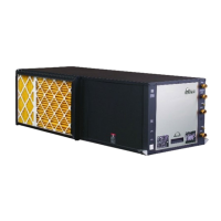
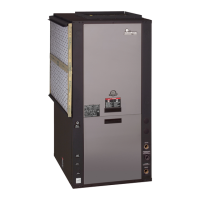
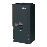

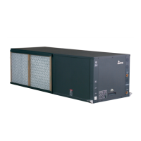
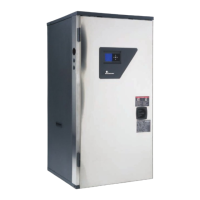
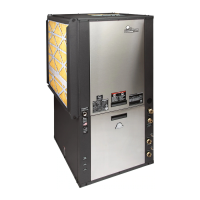


 Loading...