Do you have a question about the ClimateMaster Tranquility 27 and is the answer not in the manual?
Summarizes DANGER, WARNING, CAUTION, and NOTICE safety alert levels.
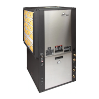
Procedures for checking shipment and unit condition upon receipt.
Guidelines for storing equipment in its original packaging and a clean, dry area.
Methods to protect units from damage and contamination on the job site during construction.
Steps and checks required before beginning unit installation, including wiring and component verification.
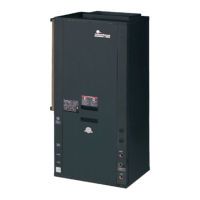
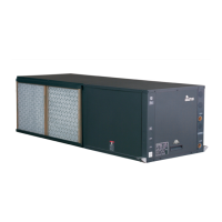
Guidance on selecting indoor locations for optimal service access and performance for horizontal units.
Instructions for using factory-installed hanger kits and proper unit suspension above ceilings.
Step-by-step instructions to convert air discharge from side to back configuration.
Step-by-step instructions to convert air discharge from back to side configuration.
Notes on limitations for converting return air configurations due to piping changes.
Requirements for installing condensate lines, traps, and venting for horizontal units.
Guidelines for sizing, connecting, and installing duct systems for quiet operation and optimal airflow.
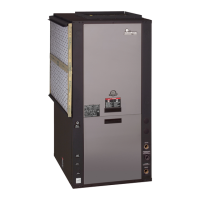
Guidance on selecting indoor locations for vertical units, considering service access and clearances.
Methods to reduce noise transmission from vertical units through room enclosure and isolation pads.
Details on condensate drain connections and internal traps for vertical units.
Instructions for mounting the external flow controller beside the unit.
Specifics on swivel piping fittings and proper tightening for water connections.
Steps for preparing the site and marking underground utilities before loop installation.
Guidelines for installing closed loop piping materials, fittings, and testing.
Procedure for flushing and purging air and debris from the earth loop system.
Requirements for using antifreeze based on entering loop temperatures and calculation methods.
Field selection of low water temperature limits for system protection by clipping jumpers.
Typical piping layout and considerations for open loop systems, including water quantity and quality.
Guidelines for assessing water quality and selecting appropriate heat exchangers.
Recommendations for sizing pressure tanks and pumps for optimal operation.
Placement and function of water control valves to prevent mineral precipitation and water hammer.
Methods for regulating water flow through the heat exchanger using valves or devices.
Setting the low temperature limit for water coils to prevent freeze damage.
Overview of the HWG control system, sensors, and DIP switch functions for setup.
Steps for preparing the hot water tank before HWG installation, including draining and flushing.
Requirements for routing and installing HWG water piping, insulation, and air vents.
Procedure for refilling the water tank and purging air from the HWG piping.
Steps for initial startup and verification of HWG system operation and performance.
Compliance with electrical codes and proper wiring practices for line voltage connections.
Guidelines for connecting incoming line voltage to the unit's contactor terminal.
How to change blower fan speed by adjusting wire connections on the motor.
Connecting power wires for the HWG pump after piping completion and air purging.
Wiring thermostats to the CXM or ECM control boards for unit operation.
Field selection of low water temperature limits by clipping jumpers for freeze protection.
Using terminal "A" to control accessory devices like water valves via 24VAC signals.
Wiring and operation of external solenoid valves, including slow-closing types and thermostat compatibility.
Design considerations for two-stage units using parallel solenoid valves for water flow management.
Proper placement and wiring of thermostats for accurate temperature measurement and unit control.
Determining cooling CFM based on tap settings and dehumidification mode.
Determining heating CFM based on tap settings for TT and TS units.
Setting CFM for auxiliary or emergency heat modes based on unit type.
Fine-tuning airflow adjustments using CFM adjust settings for optimal performance.
Field selection for humidity control via constant or automatic modes.
Understanding thermostat inputs and sensor signals for CXM control operation.
Various configuration options for the CXM control via jumpers and DIP switches.
Details on using DIP switches for unit performance settings and features.
Overview of safety features like anti-short cycle, fault retry, and lockout modes.
Using the CXM LED to understand control status and fault codes for troubleshooting.
Sequence of operation for the CXM control during unit startup, including delays.
Compatibility and signal requirements for thermostats used with CXM control.
Factors determining unit performance and acceptable environmental ranges for operation.
Specific limits for initial unit startup and building commissioning to achieve occupancy temperatures.
Pre-power checks for unit and system components before operation.
Step-by-step process for starting up the unit and verifying operation in cooling and heating modes.
Procedures for checking and cleaning water coils based on water quality and application type.
Maintenance considerations for HWG coils, especially with hard water, to prevent scaling.
Importance of clean filters for performance and instructions for cleaning/replacement.
Inspection and cleaning of condensate drains to prevent plugging and overflow.
Annual checks for compressor amperage and dry operation for preventative maintenance.
Maintenance for fan motors, advising against unnecessary lubrication to prevent dirt buildup.
Cleaning the air coil for maximum performance and care instructions for aluminum fins.
Care instructions for the unit cabinet to prevent corrosion from moisture contact.
Guidelines for servicing the refrigerant circuit and proper operating checks before intervention.
Preliminary checks to perform before consulting troubleshooting charts for operational difficulties.
General guidelines for troubleshooting the CXM control board by verifying inputs and outputs.
Verifying thermostat inputs and sensor continuity for the CXM control using a voltmeter.
Checking thermistor resistance and continuity for accurate readings and calibration.
Verifying outputs from the CXM control for compressor, fan, and electric heat circuits.
Entering test mode to check CXM control operation and diagnose faults efficiently.
Using flowcharts to diagnose operational problems and identify fault causes systematically.
Troubleshooting steps for issues related to main power supply, voltage, and connections.
Diagnosing and resolving high pressure faults indicated by Code 2 on the CXM control.
Identifying causes and solutions for high pressure conditions in the system, such as overcharging.
Troubleshooting low pressure or loss of charge faults indicated by Code 3 on the CXM control.
Diagnosing and resolving issues related to low pressure or refrigerant charge.
Troubleshooting faults related to the water coil low temperature limit (FP1) indicated by Code 4.
Identifying causes and solutions for low water temperature faults and sensor issues.
Troubleshooting faults related to the air coil low temperature limit (FP2) indicated by Code 5.
Identifying causes and solutions for low air temperature faults and sensor issues.
Troubleshooting condensate overflow faults indicated by Code 6 on the CXM control.
Diagnosing and resolving over/under voltage shutdown issues affecting the CXM control.
Troubleshooting inefficient operation detected by the UPS feature, indicated by Code 8.
Steps for troubleshooting when no specific fault code is displayed by the CXM control.
Diagnosing and resolving issues causing the unit to short cycle, such as thermostat settings.
Troubleshooting scenarios where only the fan operates, indicating potential compressor issues.
Troubleshooting scenarios where only the compressor operates, indicating potential fan or control issues.
Diagnosing why the unit fails to operate in cooling mode, checking various system components.
Addressing issues of reduced cooling or heating capacity due to airflow, charge, or sizing.
Diagnosing and resolving problems related to high head pressure, such as water temperature or charge.
Troubleshooting causes for low suction pressure, including refrigerant charge and airflow.
Identifying causes for low discharge air temperature during heating, such as airflow or charge.
Addressing issues related to high humidity levels within the space, possibly due to unit operation.
| Refrigerant | R-410A |
|---|---|
| Compressor Type | Scroll |
| COP | Up to 5.0 |
| Efficiency Rating | EER up to 30.0, COP up to 5.0 |
| Stages | Single |
| Voltage | 208/230V |
| Phase | 1 |