18
Geothermal Heating and Cooling
Tranquility
®
30 Digital (TE) Series IOM - 60Hz HFC-410A
Rev.: 29 May, 2015J
Water Out
Water In
Heat Pump
B
Water Out
Water In
Heat Pump
A
To Ground
Loop
Water Out
Water In
Heat Pump
C
Indoor Loop
Shut-Off Valve
Ground Loop
Shut-Off Valve
Flush
Valve
Size for Heat Pump
‘A’ Flow
Size for ‘A’ + ‘B’ Flow
Size for ‘A’ + ‘B’ + ‘C’ Flow
Size for
Heat Pump
‘C’ Flow
Size for
Heat Pump
‘B’ Flow
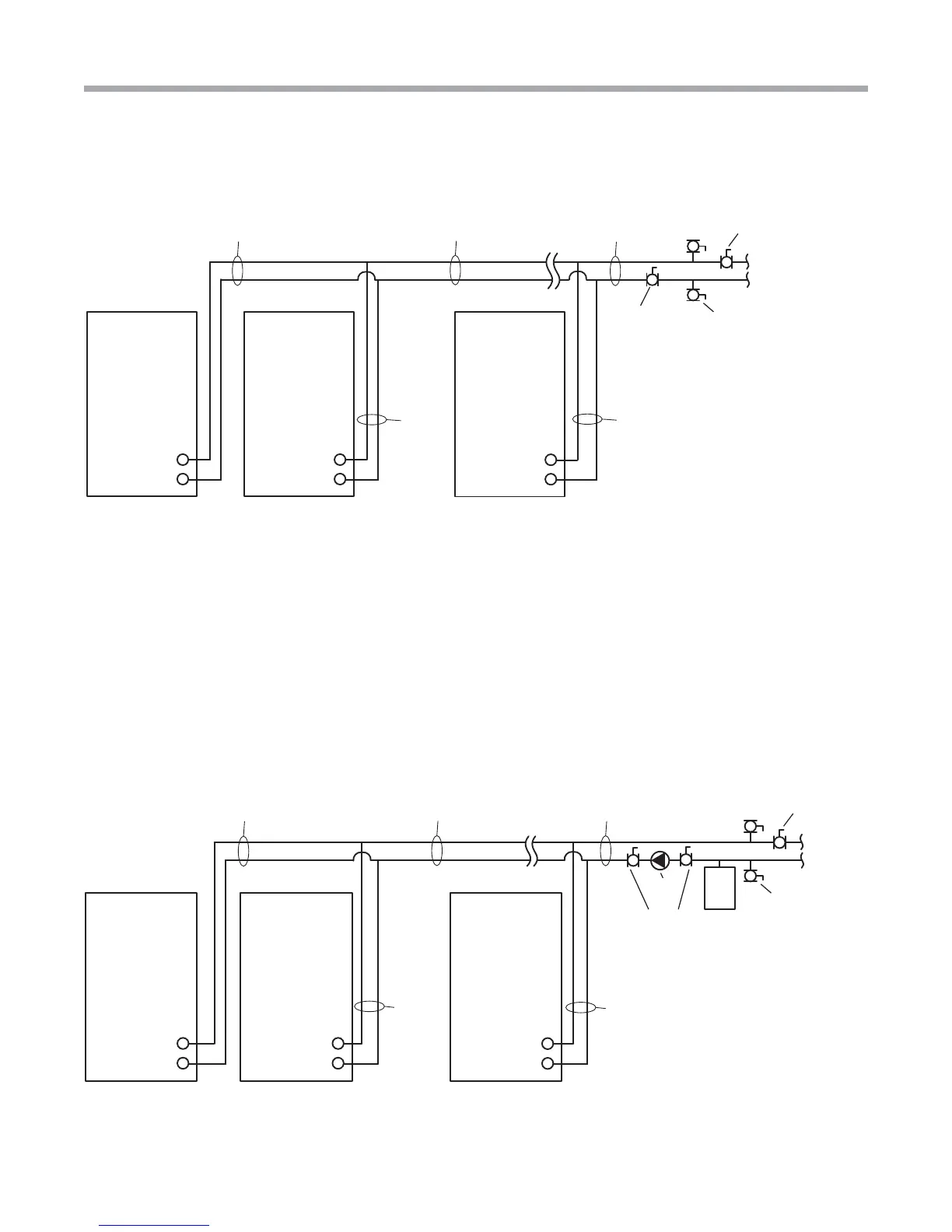
Multiple Unit Piping and Flushing
Water Out
Water In
Heat Pump
Water Out
Water In
Heat Pump
To Ground
Loop
Water Out
Water In
Heat Pump
Pump
Isolation
Valves
Ground Loop
Shut-Off Valve
Flush
Valve
Pump
Exp
Tan k
Size for
Heat Pump
‘B’ Flow
Size for Heat Pump
‘A’ Flow
Size for ‘A’ + ‘B’ Flow
Size for ‘A’ + ‘B’ + ‘C’ Flow
Size for
Heat Pump
‘C’ Flow
Figure 16b: Multiple Units with Internal Flow Controllers and External Flushing Valves
Figure 16c: Multiple Units with Internal Modulating Valves and Central Pump
Multiple Units with Internal Modulating Valves and Central Pump
This is an application where multiple units are used in conjunction with a central, variable speed pump. In this case, units with
closed loop modulating valves are used (do not use open loop modulating valves on a closed loop system). External fl ushing
valves are required. This application is for larger systems, including commercial.
Before fl ushing, the installer should manually open all modulating valves as detailed in Closed Loop – External Central
Pumping section of this manual. Next, fl ush the ground loop. The installer should close a pump isolation valve and open the
ground loop shut-off valve to prevent fl ow through the indoor loop while fl ushing the ground loop.
Once the ground loop is fl ushed, close the ground loop shut-off valve and open the pump isolation valve to fl ush the units
and indoor piping. Once the system is fl ushed remember to return the modulating valves to their normal operating position.