EasyManua.ls Logo

CLIMAVENETA HRAN 0121 - Wiring Diagram 0011-0021 Three Phase

CLIMAVENETA HRAN 0121
30 pages
Print Icon
To Next Page IconTo Next Page
To Previous Page IconTo Previous Page
Loading...
HRAT E - HRAT/HRAN
14 English 09/02
U-V-W-NPE
400V-3N~-50Hz
QF1
U-V-W-N
L1-L2-L3-N
1
3~
M
2 3
T1 T2 T3
L1
L2
L3
KM1
QM1
Z1
QS1
U
N
N4
L2
U3
U1
A1
1
0
1
12VAC
230VAC
0
14
21
22
12VAC 12VAC
POWER
32
C
1
R1
15
16
KM1
18
15
FU2
17
12DC TK ID3 ST1 ST2 ST3 ST4 GNDALL GND
ALARM ANALOG INPUTDIGITAL INPUT
1
E
3 42
6 7 8 914 15
F3SA1 SA2
3
F
1 2 4 5 6
10 11
+to
BT1
+to
BT2
+po
BP3
bianco
marrone
RD1
230/24VAC 500mA MAX
1
R2
DIGITAL OUTPUT
D
5
6
YV1
KA2 KM1
1~
M
16 17
E1
KA2
1~
M
A
1 2 3 4 5 6 7
EV1
U1 Z1 U2 Z2
15
KA1
1 2 3
KEYB
26
24 25
A2
5 64
24VAC
230VAC
3
TC1
19 2018
A6
KA1
4 5
5 6
17
33
15
42
42
33
4
0
3
3
0
0
3
3
42
33
0
20
0
19
21
22
30
32
33
35
36
38
39
40
41
42
FU1FU4
32
42
34
32
33
30
KA1
35
36
17
44
15
37
42
36
42
39
42
40
30
38
42
39
40
38
41
42
2727
2828
23 23
2424
25
26
47
46
45
25
29
45
46
47
15
23
15
24
15
2
17
3 4 5 6
C2
1
0
26
18
15
23
24
15
7 8
3
9
27
28
27
28
ID4
37
34
ID5
34
F5
ID1
F1F2
ID2
32
33
42
36
44
34
30
39
40
38
41
42
45
46
47
33
15
42
30
42
20
0
MORSETTI PER INSTALLATORE
INSTALLATOR TERMINAL BOX
42
41
FU3
2
2
3
4
0
3
3
0
2
45
46
47
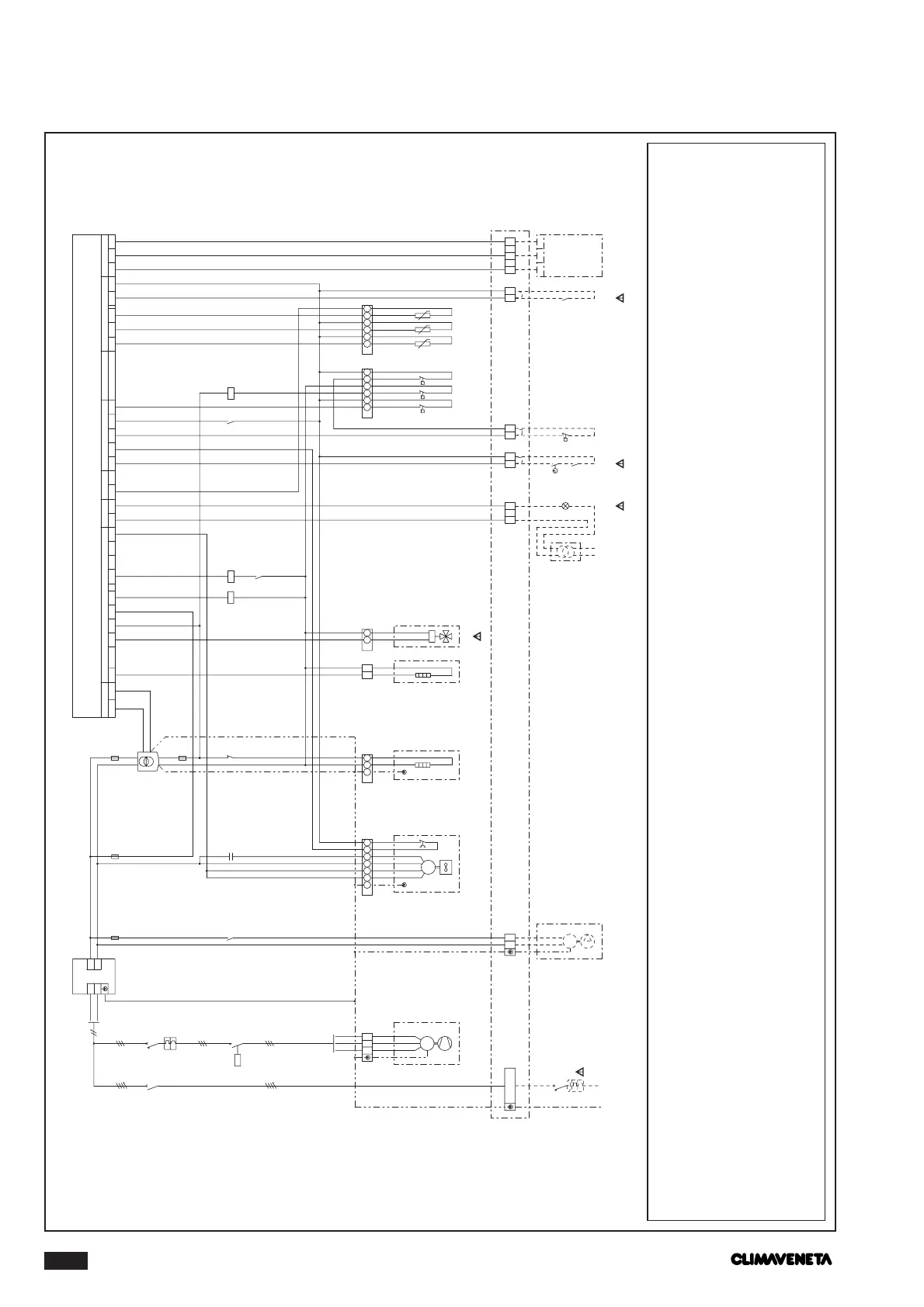
WIRING DIAGRAM 0011-0021 THREE PHASE
Factory installed components
A1 Radio interference suppresser
A2 Electronic controller
A6 Unit control display keyboard
BP3 Condensing/evaporation control pressure transducer
BT1 Installation water inlet temperature sensor
BT2 Installation water outlet temperature sensor
C1 Compressor start capacitor
C2-3 Fan start capacitor
E1 Water pump
EV1-2 Fans
F1 High pressure switch
F2 Low pressure switch
F3 Flow switch
F5 Water differential pressure switch
FU1 Transformer protection fuse
FU2 Auxiliary circuit fuse
FU3 Fan protection fuse
FU4 Water pump protection fuse
KA1 High pressure switch relay
KA2 Water pump control relay
KM1 Compressor contactor
QF1 Chilling assembly protection switch
QM1 Compressor thermal overload switch
QS1 Door lock disconnector switch
R1 Compressor oil sump heater
R2 Frost heater
RD1 Red lockout warning light
SA1 On-off switch and/or timer input
SA2 Summer-winter switch input
TC1 Safety transformer
YV1 Cycle reversal valve
Z1 Compressor
1 Switch not included in the supply
3 Heat pumps only
4 Lights not supplied
5 Optional on-off switch and timer
6 Optional summer-winter switch; for cooling-only mod-
els terminals 8-9 closed

Related product manuals