HRAT E - HRAT/HRAN
7English 09/02
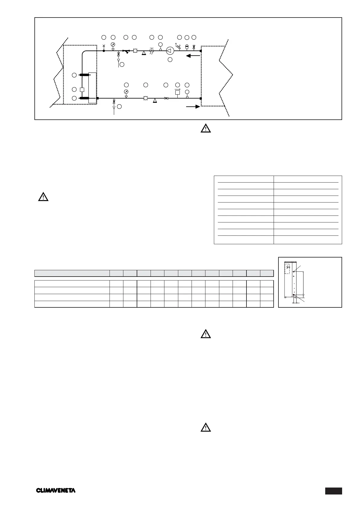
SIZE AND LOCATION OF CONNECTIONS
Model
0011 0021 0025 0031 0041 0051 0061 0071 0091 0101 0121 0151
If the installation requires a useful head higher than that
obtained by installing a pump assembly and storage tank,
it is recommended that an additional pump is installed
on the unit.
The pump can be easily installed on the unit by removing
the special pipe stub provided. Connect to terminal 4, 5
on the electrical panel.
The chillers must be provided with a filling/top-up
system connected to the return line and a drain cock
in the lowest part of the installation. Installations con-
taining anti-freeze or covered by specific legislation
must be fitted with hydraulic disconnectors.
The manufacturer is not liable for obstruction,
breakage or noise resulting from the failure to
install filters or vibration dampers.
Particular types of water used for filling or top-
ping up must be treated with appropriate treatment
systems. For reference values, see the table.
FILLING THE INSTALLATION
- Before filling, check that the installation drain cock is
closed.
- Open all installation and terminal air vents.
-Open the gate valves.
- Begin filling, slowly opening the water filling cock outside
the unit.
-When water begins to leak out of the air vent valves of
the terminals, close them and continue filling until the
pressure gauge indicates a pressure of 1.5 bars.
The installation must be filled to a pressure of
between 1 and 2 bars.
It is recommended that this operation be repeat-
ed after the unit has been operating for a number
of hours.The pressure of the installation should be
checked regularly and if it drops below 1 bar, the
water content should be topped-up.
Check hydraulic connections for tightness.
PH 6-8
Electrical conductivity less than 200 mV/cm (25°C)
Chlorine ions less than 50 ppm
Sulphuric acid ions less than 50 ppm
To tal iron less than 0,3 ppm
Alkalinity M less than 50 ppm
Total hardness less than 50 ppm
Sulphur ions nil
Ammonia ions nil
Silicon ions less than 30 ppm
EMPTYING THE INSTALLATION
- Before emptying, place the general installation switch in
the “off” position.
- Make sure the installation fill/top-up water cock is
closed.
-Open the drain cock outside the unit and all the installa-
tion and terminal air vent valves.
If the fluid in the circuit contains anti-freeze,
it should be not be allowed to drain freely as it is
pollutant. It should be collected for possible reuse.