drawings
Climbing Technology by Aludesign S.p.A. via Torchio 22
24034 Cisano B.sco BG ITALY www.climbingtechnology.com
2/24
IST12-2D651CT_rev.8 10-21
Ø12 mm
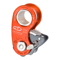
TECHNICAL DATA
MODEL
ALPINE UP KIT
REF. No.
2K651
WEIGHT
175 g (only device)
ROPE
FOR USE WITH ROPES EN892
½
half / twin ropes Ø 7.3 ÷ 9 mm
1
single rope Ø 8.6 ÷ 10.5 mm.
ATTENTION! The term “rope” can mean
one or two strands of rope. When using
half or twin ropes, each strand of rope must
pass through its separate rope slot. The term
“Prusik” is used for indicate any self-locking
knot for climbing.
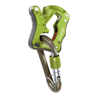
CONNECTOR
YOU MUST USE:
the included hot forged light alloy
karabiner Concept SGL HC with hard
coat anodization. It presents a spring
bar which prevents the possibility
of the cross loading. You must use it,
connected to the belay loop of the
harness, during the use in CLICK UP or
DYNAMIC MODE. During the belaying
of 1-2 seconds, you must use it on the
anchor point (I).
TEST OF THIS
DEVICE MADE BY
VVUU a.s.
NOTIFIED BODY “1019”
Pikartska 1337/7 716 07
Ostrave - Radvanice
CZECH REPUBLIC
1
2
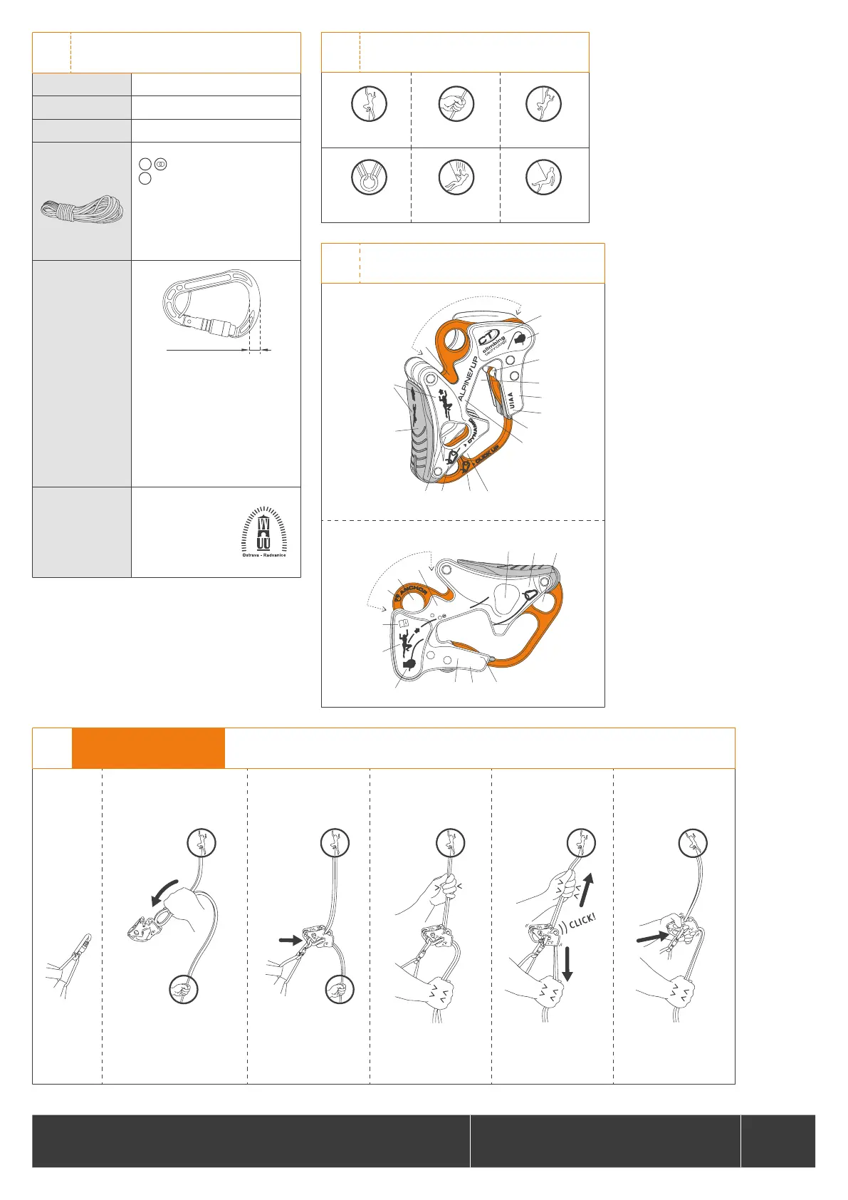
LEGEND
2.1 - leader 2.2 - hand 2.3 - second
2.4 - anchor 2.5 - fall 2.6 - lowering
76
F
D
C
2
1
E
B
A
8
G
H
3
4
5
RO PE E N8 92
1
Ø 8. 6÷ 10 .5 m m
½
Ø
7. 3÷ 9 mm
BB YY
PA T EN T E D
MA DE I N I TA LY
I
9
B
17
16
15
14
10
RO PE E N8 92
1
Ø 8. 6÷ 10 .5 m m
½
Ø
7. 3÷ 9 mm
BB YY
PA T EN T E D
MA DE I N I TA LY
13
12
NOMENCLATURE / MARKING
Each side presents a mode of use.
3.1 - SIDE A
3.2 - SIDE B
3
This mode is ideal for use on well-equipped multi-pitch sport climbing routes with fi xed anchors, such as bolts or glue-in an-
chors. A safety check between the climber and the belayer is essential before start climbing!
4.1
SETUP
4.2
SETUP
4.3
SETUP
4.4
SETUP IS OK!
4.5
LOCKING TEST
4.6
RELEASE
Connect the
karabiner to
the belay loop
of the harness.
Insert the loop of the rope in the slot
B, referring to symbols 2-6-8 on the
device. With single rope, use the
slot opposite the karabiner gate.
Insert the karabiner in the
hole F with the rope inside.
Close the karabiner gate!
The system is OK.
From now on always hold
the free end of the rope in
your hand!
Check the device works
correctly before use, verifying
that it locks the rope with a
typical “CLICK” sound.
To start belaying a leader,
push the device forwards
to return the karabiner to
position F.
4
CLICK UP MODE
INSTALLATION AND SETUP