Climbing Technology by Aludesign S.p.A. via Torchio 22
24034 Cisano B.sco BG ITALY www.climbingtechnology.com
10/24
IST12-2D651CT_rev.8 10-21
ENGLISH
The instruction manual for this device consists of general and specific instructions,
both must be carefully read and understood before use. Attention! This leaflet
shows the specific instruction only.
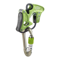
SPECIFIC INSTRUCTIONS ALPINE UP (PATENTED).
1) FIELD OF APPLICATION. Alpine Up is a belay / rappel device for mountain-
eering and sport climbing routes with one or more pitches that can be used with
single, half or twin ropes. It has two belaying modes, depending on the type of
terrain: CLICK-UP MODE (hand-assisted braking). For use on well-equipped sport
climbing routes with fixed anchors, such as bolts or glue-in anchors, and for sport
climbing and indoor climbing wall. Warning! Not suitable for use on traditional
climbing routes and adventure terrain; DYNAMIC MODE (manual braking). For
adventure terrain and traditional climbing routes with nuts, friends, pitons etc.
2) NAMES / MARKINGS. The side A of the device has markings for belaying
the leader in two modes, the side B has markings for belaying 1 or 2 second
climbers.
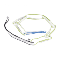
2.1 - Names of the parts. A) Braking groove (for use in case of error). B) Rope
loop insertion slots. C) Resistance lock cam. D) Braking area. E) Spring bar. F)
Hole for CLICK UP MODE karabiner. G) Hole for DYNAMIC MODE karabiner.
H) Ergonomic lever for abseiling / rappelling. I) Hole for belay station karabiner.
G) Hole for belaying karabiner. L) Hole for release karabiner.
2.2 - Markings. 1) Name of the manufacturer or of the responsible for the intro-
duction in the market. 2) Hand side. 3) EN 15151-2:2012 type 2: norm with
which Alpine Up is compliant. 4) UIAA logo. 5) Product name. 6) Hole for CLICK
UP MODE karabiner. 7) Hole for DYNAMIC MODE karabiner. 8) Climber side.
9) Hole for belay karabiner. 10) Compatible rope diameters and types. 11)
Karabiner hole for belaying second climbers. 12) Patented device. 13) Country of
fabrication. 14) Batch number (BBYY) composed of production batch number (BB)
and year of manufacture (YY). 15) Hand side. 16) Second climber side. 17) Logo
informing the user to read the attached user instruction carefully.
3) CHECK INSPECTION POINTS. Prior to each use, it is necessary to check that
all the tool components are in excellent condition, without excessive wear and
tear, cracks and/or burrs. Particularly check the braking area (D) and the resist-
ance lock cam (C), and ensure that the spring bar (E) and the ergonomic lever
(H) can fully depress and release smoothly, without sticking. Check that the HMS
karabiner is not worn out in its rope sliding section.
4) COMPATIBILITY (Fig. 1).
Make sure the device is compatible with the other elements used.
4.1 - Ropes. Alpine Up is used with EN892 dynamic ropes: half and twin ropes
Ø 7.3÷9 mm; single ropes Ø 8.6÷10.5 mm. Braking efficiency and ease of
rope feed depend on the diameter and smoothness of the rope. Attention! The
use of wet or icy ropes can affect the efficiency of the device. Attention! In case
of use with two ropes, only use ropes having the same diameter and state of
consumption. Attention! The self locking abseil with a single rope is not allowed.
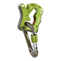
4.2 - Belay karabiner. A CONCEPT SGL hot-forged light-alloy karabiner with
hard anodized finish must be used. It has an anti-wear surface and a spring bar
to prevent cross-loading. This karabiner, connected to the belay loop on the har-
ness, must be inserted in holes F (CLICK-UP MODE) and G (DYNAMIC MODE).
When belaying 1 or 2 seconds, it must be connected to the belay station and
positioned in hole I.
4.3 - Karabiner for belaying seconds. When belaying 1 or 2 seconds, a wide-
base HMS karabiner must be used in the hole G. Warning! The karabiner must
be able to rotate around the base of the device (Fig. 11.2).
4.4 - Additional karabiners. For controlled release the rope of a second, insert a
quickdraw karabiner (Fig. 11.7) in hole L. For the self locking abseil - facilitated
mode, use preferably an HMS carabiner with a wide base, inserted in the hole
I (Fig. 9.1).
4.5 - Terminology. In this note, the term “rope” refers to one or two ropes. When
half or twin ropes are used, each one must pass through its own slot B in the
Alpine Up. The term “Prusik” is used for indicate any self-locking knot for climbing.
5) CLICK-UP MODE - INSTALLATION AND SETUP.
5.1 - Installation. Connect the karabiner to the belay loop on the harness, open
the bar and insert the belay loop (Fig. 4.1). Insert the loop of rope in the slots B
in the Alpine Up, referring to symbols 2-6-8 on the device (Fig. 4.2). Insert the
karabiner in the hole F with the rope inside (Fig. 4.3). The system is now ready for
use (Fig. 4.4). Warning! With a single rope, use slot B in the Alpine Up opposite
the karabiner gate.
5.2 - Function test (Fig. 4.5). Check the device works correctly each time before
use. When you have connected the Alpine Up to the harness, hold the free end of
the rope in one hand and pull the climber’s rope upwards with the other, checking
it locks the rope on the device with a typical “CLICK” sound.
5.3 - Releasing the device (Fig. 4.6). To start belaying the leader, or paying out
rope to the second after a stopping a fall, hold always the free end of the rope
in one hand and grip the Alpine Up in the other hand, as shown. Then push it
forwards to return the karabiner to position F.
6) CLICK-UP MODE - BELAYING THE LEAD CLIMBER.
Before setting out, the lead climber must be safely anchored and check that the
Alpine Up works correctly. Make sure the leader’s knot is correct and the rope is
uncoiled. Stand in a convenient position so as not to hinder operations. Warning!
Remember to hold the free end of the rope in your hand at all times! Risk of death!
When ascending a multi-pitch route, before setting up on a new pitch, the leader’s
rope rope must pass through a directional anchorage on the belay point. If not,
the Alpine Up may not work if the lead climber falls (figs. 5.6 and 5.7).
6.1 - Feeding the rope (Fig. 5.1). With one hand, bend the free end of the rope
and feed it through the Alpine Up. With the other pull and feed the climber’s rope
through the device, keeping the karabiner in position F. Always hold the free end
of the rope in one hand!
6.2 - Taking up slack (Fig. 5.2). With one hand pull and feed the free end of the
rope through the Alpine Up. With the other pull the climber’s rope towards the
device. Always hold the free end of the rope in one hand!
6.3 - Arresting a fall (Fig. 5.3). Hold the free end of the rope firmly in one hand
and pull it downwards. The device will lock the rope, with a typical “CLICK”
sound. Do not hold the Alpine Up in your hands. Always hold the free end of the
rope in one hand!
6.4 - Lowering the climber (Fig. 5.4). Activate the device in lock mode, as indi-
cated under point 6.2. Still holding the free end of the rope in one hand, open
the lever H and push it downwards, as shown. Lower the climber to the ground,
accompanying the free end of the rope towards the device. When the climber is
down, release the device as instructed under point 5.3. Warning! Do not pull the
lever down: the system would not allow lowering.
7) ALWAYS SAFE, EVEN IN THE EVENT OF AN ERROR.
The device will not work properly in the event of the installation errors (figs. 6.1-
6.3). If this happens, stop the ascent immediately and lower the climber as follows
(figs. 6.2-6.4). Place the rope in the braking groove A and accompany it towards
the device with both hands, alternating them downwards, lower the climber to
the ground.
8) BELAY ON TOP ROPE. Warning! Remember to hold the free end of the rope in
your hand at all times (Fig. 7.3)!
8.1 - Installation (Fig. 7.1). Install and activate the device in lock mode, as
instructed under point 5.2. Check the climber’s rope-connecting knot is correct.
8.2 - Belaying (Fig. 7.2). With one hand pull and feed the free end of the rope
through the device, with the other pull the climber’s rope towards it, taking up
slack during ascent. If the climber falls or stops to rest, the system remains active
in rope-lock mode.
9) SELF-LOCKING ABSEIL. Before descending, belay yourself to the belay station
using a sling fixed securely onto the harness. Prepare the descent rope and make
sure it is properly unwound and there is knot at the end.
9.1 - Installation (Fig. 8.1-8.2). Install the device in the sling at a minimum dis-
tance of 20 cm and activate it in lock mode, as instructed under point 5.2.
Warning! In this case the “climber side” symbol (8) identifies the end of the rope
in the anchor point direction (Fig. 8.1).
9.2 - Locking and tensioning (Fig. 8.3). Take up the slack as instructed under point
6.2 and use you own weight to tension the ropes and the system.
9.3 - Releasing the sling (Fig. 8.4). Holding the free end of the rope in one hand,
release the longe karabiner with the other.
9.4 - Abseiling (Fig. 8.5). Holding the free end of the rope in one hand, open
the lever H (1) with the other, pressing on it and rotating the device upwards (2),
as shown. Descend, pulling the free end of the rope towards the device. Atten-
tion! Do not pull the lever and device downwards as this would keep the system
braked.
10) SELF LOCKING ABSEILING - FIRST USES. When using Alpine Up for the first
time, it is advisable to use a Prusik knot on the rope below the device to practice to
abseiling (Fig. 9.1). Follow points 9.1 to 9.4. Proceed with the descent, keeping
the knot unloaded. Warning! Install Alpine Up at a distance that will prevent it
from interfering with the Prusik knot.
11) SELF LOCKING ABSEILING - FACILITATED MODE.
There are some situations in which the abseiling can be quite difficult: high weight
of the ropes that are entirely hanging in a void; low weight of the climber (for ex.
children, young people, women); unfavourable ratio between the weight of the
climber and the weight of the ropes lying below the device. If any of the above
described cases occurs, it is necessary to relieve the load of the ropes from the
Alpine Up, in order to make smoother the descent. To perform this action, one of
the following methods must be applied: A - lift progressively the free end of the
ropes placed below the device, enough to allow a smooth descent; B - carry on
the following operations: install the Alpine Up as indicated under points 9.1-9.2
and insert an additional carabiner in the hole I (Fig. 10.1). Insert the ropes inside
the carabiner (Fig. 10.2), close the gate and follow the indications described
under points 9.3-9.4, Proceed with the descent as explained under point 9.4
(Fig. 10.3). Attention! It is possible to use this mode at any time during every
self-locking abseiling.
12) DYNAMIC MODE - INSTALLATION AND SET-UP.
12.1 - Installation. Connect the karabiner to the belay loop on the harness, open
 Loading...