M23740N6-03 01/10/07 page 15
FUNCTIONAL CONNECTIONS
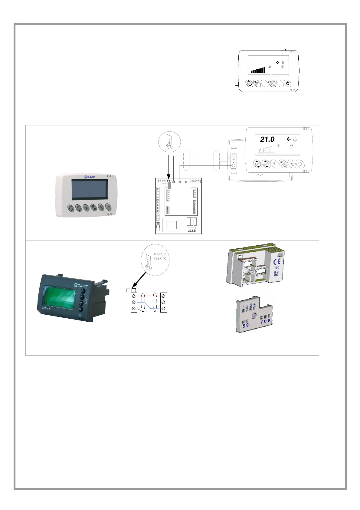
FOR UNIT WITH TERMINAL SPACE ELECTRONICS
(unit with CTS option) HID-T2, HID-T3 or HID-TI2 THERMOSTAT
21.0
REMOTE
ECO
AUT O
E
o
e
a
n
The TERMINAL SPACE electronics can be coupled to the ambient controls below indicated.
In both cases the type of cable used must be 2x0.35 mm
2
with shield on the gnd.
Max distance: 15m
HID-T2 electronic ambient control
TEMPERATURE probe management (HID-T2)
OR TEMPERATURE + HUMIDITY (HID-T3)
+
2
1
4
5
3
-
gnd
12 11 10
+ -- gnd
Built-in electronic ambient
control HID-TI2
9
8
7
+
-
NET
12
11
10
UNIT
THERMOSTAT
The recessed room control is supplied with a series of supports that make it possible to adapt it to the main civil series
of plates: refer to the instructions provided with the thermostat.
POSITIONING OF THE ROOM THERMOSTAT
The selection of the place of installation is decisive for room comfort and energy consumption.
The thermostat must be positioned:
• in a room with average temperature and humidity that are representative of other rooms
• at a height of 150 cm
• preferably on an internal wall
Positions to avoid:
• near sources of heat (lamps, computers, etc.)
• exposed to direct sunlight
• in a position in the direct flow of air from outlets of diffusers
• behind curtains of pieces of furniture
• near doors and windows to the outside
• on walls where there are chimneys or heating pipes
• on external walls