M23740N6-03 01/10/07 page 16
ELECTRICAL CONNECTIONS TO BE HANDLED BY THE CLIENT
For all connections refer to the electrical diagram supplied with the unit.
• REMOTE ON – OFF
• Modulating valve H2O (power supply 24V to be provided for by the client).
It is possible to control one valve only (2-pipe-systems) or two different valves for heating and cooling (4-pipe-
systems)
• Fresh air Shutter
• Room thermostat
• RS485 serial line (refer to document RS 485 NETWORK GUIDELINES)
• Electrical resistance section
If present, the electrical resistances must be enabled by modifying the following parameters:
P24 = 3 enables INPUT 2 as resistance thermal alarm
P27 = 1 main heating element
P53 = 3 signal 0-10V
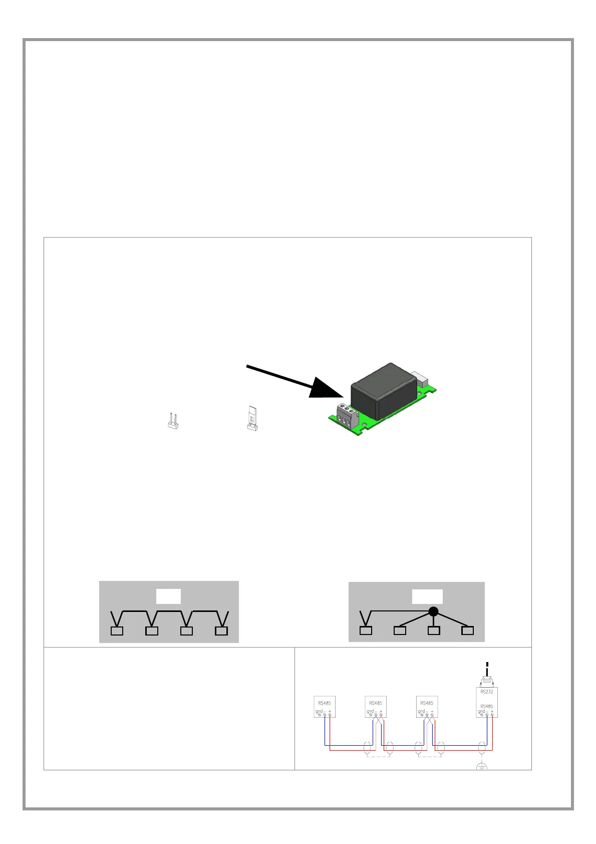
RS485 SERIAL PORT
If Clivet provides only the units with BMS communication port (installed or provided separately), it is responsible only for
the units themselves and not for the units downstream. Therefore CLIVET is not responsible for operations such as
choice and installation of cables, connection, serial addressing and checks on network functionality.
On request, Clivet provides the specifications for the communication protocol of its units and the necessary guidelines to
connect them to RS485.
The card for RS485 serial line must be connected to the main card using the appropriate wire provided.
The network termination jumper alongside the screw terminal board for the connection of 485 must be inserted if the unit
is the last one in the network.
JUMPER :
DISINSERITO - INSERITO
Following some indications for the serial connection ; refer anyway to the CLIVET “RS 485 NETWORKS.
- The total length of each serial line, has not to be
more than 1000 metres
- The potential difference between the “earths” of
two RS485 devices must be lower than 7 V
- Twisted and shielded couple of conductors
- Conductor section 0.22mm2…0,35mm2
- Nominal capacity among the conductors < 50
pF/m nominal impedance 120 Ω
- Recommended cable BELDEN 3105 A
TYPE OF NETWORK
The serial lines must be connected in bus typology, i.e. nodes to more points are not admitted.
OK
NO !
SHIELD
- It must be connected to a ground with no troubles
- Connected to the round in only one point
- The shield continuity must be kept constant during
all the serial shield extension.
Sistema di supervisione
Supervision system

 Loading...