Set and use supportive angle steel.
Steel beam and girder structure
Suspended bolt
Pendant bolt
Supportive angle steel
Set it with embedded bushes or embedded bolts.
New concrete roughcast
Flap type inser Slide type inser
Concrete iron
Embedded bolt
(With embedded
bolt in pipe)
Fig. 3-2
3.4 Installation
Before installation, please confirm all external parts are
stand in their place and without damage.
The surrounding environment of the unit, especially the
sides of wiring cabinet and water collecting side should
reserve sufficient wiring and maintenance and space;
additionally, one should ensure the removing space for
filter griller.
Unit should mount steadily and without sustain the weight
form condensate water pipe and air duct. The vents of air
inlet/outlet and return should be connected with flexible
tube.
Unit in AC 220-240V/50Hz, reliable grounding; each one
possesses of independent cut-off and protection device.
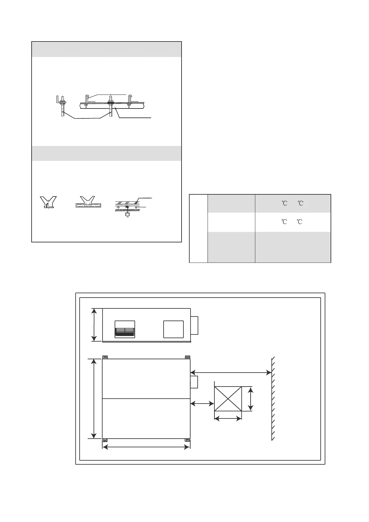
The installation dimension and maintenance space. (See
the following attached picture Fig.3-3 )
Unit:mm
Operating conditions
For proper performance, run the air conditioner under the
following temperature conditions:
Outdoor air TEMP
.
Room TEMP
.
Room humidity
-7 ~43
0 ~43
Lower than 80%
If higher than 80%, the surface of
indoor unit may be condensed or
the condensate will be blown from
air outlet.
Protection or error may occur if running the unit beyond the above
condition, and will cause unit stop running.
OPERATION
●
●
●
●
●
●
H
450
054
1000
400
Maintenance space
L
W
Communication wiring between the indoor and outdoor units
The HRV and outdoor units communicate via the RS485 serial port.
The communication wiring between the HRV and outdoor units should be connected one unit after
another in a daisy chain from the outdoor unit to the final HRV unit. And the shielded layer must be
properly grounded, and a build-out resistor must be added to the last HRV unit to enhance the stability
of the communication system.
Incorrect wiring such as a star connection or a closed ring will cause instability of the communication
system and system control anomalies.
Use a three core shielded wire (greater than or equal to 0.75 mm2) for the communication wiring
between the indoor and outdoor units. Make sure the wiring is connected correctly. The connecting lead
for this communication wire must come from the master outdoor unit.
All shielded wiring in the network are interconnected, and will eventually connect to earth at the same
point " ”.
Communication wiring between the indoor unit and wired controller
The wired controller and the indoor unit can be connected in different manners, depending on the forms of
communication.
1. For a bidirectional communication mode:
Use 1 wired controller to control 1 indoor unit or 2 wired controllers (one master and one slave
controller) to control 1 indoor unit.(see Fig.4-4)
Use 1 wired controller to control multiple indoor units or 2 wired controllers (one master and one slave
controller) to control multiple indoor units. The maximum number of connections is 16.(see Fig.4-5)
2. For single direction communication mode:
Use 1 wired controller to control 1 indoor unit
The X1/X2, D1/D2 ports on the sides of the main control board and single direction communication port
are for different types of wired controllers.
For the specific connection method, refer to the instructions in the corresponding wired controller
manual to carry out the wiring and connections.
Handling the Electrical Wiring Connection Points
Once the wiring and connections are done, use tie straps to secure the wiring properly so that the
connection joint cannot be pulled apart by external force. The connection wiring must be straight out so
that the cover of the electrical box is level and can be closed tightly.
Use professional insulation and sealing materials to seal and protect the perforated wires. Poor sealing
may lead to condensation, and entry of small animals and insects that may cause short circuits in parts
of the electrical system, causing the system to fail.
multiple indoor units (see Figure 7.8);
 Loading...